
A controller communication delay compensation method

A delay compensation and controller technology, applied in program control, computer control, general control system, etc., can solve the problems of customer economy and use sensory influence, influence customer processing, consume manpower time, etc., to save manual debugging time, debugging It is convenient and quick, and the effect of improving debugging efficiency

Active Publication Date: 2022-03-15
新代科技(苏州)有限公司
View PDF8 Cites 0 Cited by
  • Summary
  • Abstract
  • Description
  • Claims
  • Application Information

AI Technical Summary

Problems solved by technology

This debugging process consumes a lot of manpower and time, finds difficulties, and takes time to debug
At the same time, it greatly affects customer processing, wastes customer time, and wastes workpieces for testing, which has a certain impact on customer economy and sense of use.

Method used


Image

  • A controller communication delay compensation method
  • A controller communication delay compensation method

Examples


Embodiment

[0035] This embodiment is a controller communication delay compensation method, which includes the following steps:

[0036] S1) The controller is used as the upper computer to connect the driver A and the driver B through the M3 protocol communication, the driver A drives the A-axis to move, and the driver B drives the B-axis to move;

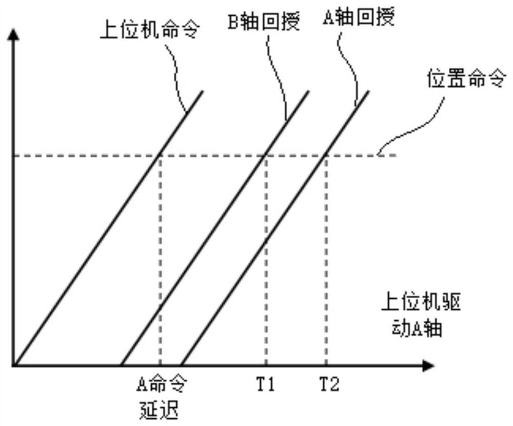
[0037] S2) The controller sends a position command to the driver A, and records the position feedback values ​​of the A-axis and the B-axis, which are respectively T1 and T2, such as figure 1 shown;

[0038] S3) When the system sends a command to driver A, calculate the time parameter T1 from the position command to the B-axis feedback:

[0039] T1 = serial delay + A command delay + B feedback delay + servo lag,

[0040] in,

[0041] The serial delay is the delay caused by the influence of the wire, which refers to the delay caused by factors such as the material and length of the M3 communication line or encoder line required for communica...


PUM


Abstract

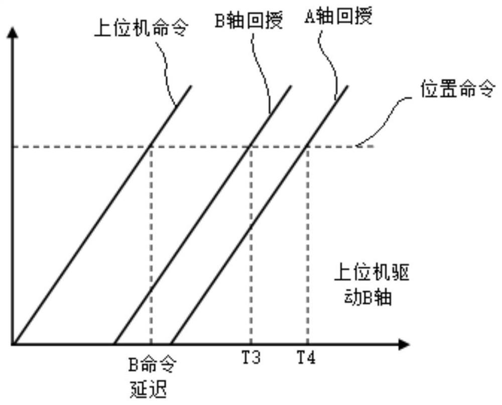
The invention discloses a controller communication delay compensation method. The controller sends out position commands to the A axis and the B axis separately, and records the corresponding command delay and feedback delay respectively, and obtains the two axes of the A axis and the B axis through calculation. The difference between the feedback delay time and the command delay time, and then generate the command delay core error, compensate the command delay core error into the system, and then repeat the above steps to minimize the feedback delay error continuously. When the feedback When the delay error is stable at the minimum state, the corresponding command delay core error is the correct communication delay error compensation value, and then the value is compensated to the system to process the product. The present invention can directly write the method into the controller as a functional program module to realize automatic communication delay compensation, effectively solve the processing problem of production due to communication delay, and effectively improve the processing quality.

Description

【Technical field】 [0001] The invention belongs to the technical field of processing control systems, in particular to a controller communication delay compensation method. 【Background technique】 [0002] In the field of machine tool processing and manufacturing, there are many types of servo drives, and different brands of drives can be mixed and matched, which makes the servo matching more diverse. At the same time, when using a machine tool with different internal servo coordination, when the product produced by the machine tool requires multi-axis coordinated motion for processing, and in the case of relatively complex processes such as flying car and tapping, the processed workpiece may have a series of Processing problems, such as tool marks, deformation, etc., the main reason for these processing problems is communication delay. The reason for this kind of communication delay is that when different kinds of servos cooperate with communication, there will be time and o...

Claims


Application Information

Patent Timeline
Patent Type & Authority Patents(China)
IPC IPC(8): G05B19/404
CPCG05B19/404G05B2219/31445
Inventor 倪迎晖陈波徐兵李宝玉阚建辉陈朋王孟沅周俊伟邱子轩冯常州陆鑫王玉星丁帅奇魏开旭王彬彬杨航李小波李健王立言
Owner 新代科技(苏州)有限公司
Learn More