Cable collecting frame used in field of housing construction engineering

A technology for housing construction projects and collection racks, applied in the field of cable collection racks, can solve the problems of different lengths of cables, difficulty in collection, and difficulty in temporarily accessing cables, etc., and achieve the effect of reducing labor force.

Inactive Publication Date: 2021-06-15
钱根新
View PDF0 Cites 3 Cited by
  • Summary
  • Abstract
  • Description
  • Claims
  • Application Information

AI Technical Summary

Problems solved by technology

[0003] In the construction of housing construction, cables are often used. Lay them before use, cut out the required length, and then install and connect them according to specific construction requirements; during construction, if there is a temporary stoppage or suspension due to rain During the operation, it needs to be placed temporarily, but the cables to be placed may be of different lengths, which is very difficult for temporary collection
[0004] On the other hand, if winding and collecting are carried out by winding wheels, in order to improve the collection efficiency, cables of different lengths need to be wound from end to end in sequence, but this winding method is not easy to temporarily access the cables of a specific length wound on the collection rack, For example, the cable taken is at the innermost part of the winding

Method used


Image

  • Cable collecting frame used in field of housing construction engineering
  • Cable collecting frame used in field of housing construction engineering
  • Cable collecting frame used in field of housing construction engineering

Examples


Embodiment Construction

[0045] The specific implementation manners of the present invention will be further described in detail below in conjunction with the accompanying drawings and embodiments. The following examples or drawings are used to illustrate the present invention, but not to limit the scope of the present invention.

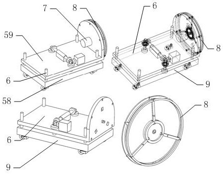
[0046] Such as figure 2 Shown, it comprises traveling mechanism 58, elevating mechanism 59, collection frame 8, and wherein elevating mechanism 59 is installed on the upper side of running mechanism 58, and collecting frame 8 is removably installed on an end of elevating mechanism 59.

[0047] Such as image 3 Shown, above-mentioned walking mechanism 58 is made up of walking platform 9 and four universal wheels 12 installed on the four corners of walking platform 9 lower sides. The convenience of using the collection frame 8 is improved by the designed traveling mechanism 58 .

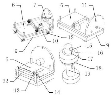
[0048] Such as image 3 As shown, above-mentioned lifting mechanism 59 comprises guide bar ...


PUM


Abstract

The invention belongs to the technical field of cable collection, and particularly relates to a cable collecting frame used in the field of housing construction engineering. The cable collecting frame comprises a walking mechanism, a lifting mechanism and a collecting frame body. After a cable is taken down, a third motor is lifted through a handle, three limiting plates which are installed on a third motor shell and provided with fork-shaped heads are inserted into three telescopic outer sleeves correspondingly, a motor shell is fixed, and a second square shaft on an output shaft of the third motor is matched with a square hole in a rotating disc; the output shaft of the third motor is fixed to the collecting frame body through a second limiting disc, then the third motor is controlled to drive the rotating disc to rotate, and in the rotating process, the cable on an outer layer of a blank area left after the cable is pulled and taken away is tensioned and wound around an inner layer, and after winding is finished finally, the tail end of the cable at the outermost side is straightened; and compared with the mode that the collecting frame is reinstalled on an output shaft of a first motor, using is more convenient.

Description

[0001] Technical field [0002] The invention belongs to the technical field of cable collection, and in particular relates to a cable collection rack used in the field of house construction. Background technique [0003] In the construction of housing construction, cables are often used. Lay them before use, cut out the required length, and then install and connect them according to specific construction requirements; during construction, if there is a temporary stoppage or suspension due to rain During the operation, it needs to be placed temporarily, but the cables to be placed may be of different lengths, which is very difficult for temporary collection. [0004] On the other hand, if winding and collecting are carried out by winding wheels, in order to improve the collection efficiency, cables of different lengths need to be wound from end to end in sequence, but this winding method is not easy to temporarily access the cables of a specific length wound on the collection ...

Claims


Application Information

Patent Timeline
Patent Type & Authority Applications(China)
IPC IPC(8): B65H75/38B65H75/44
CPCB65H75/38B65H75/44
Inventor 钱根新
Owner 钱根新
Why Eureka
Try Eureka