
Reactive power margin distribution method for AVC system

A distribution method and margin technology, applied in reactive power compensation, AC network voltage adjustment, single-network parallel feeding arrangement, etc., can solve the problem that cannot satisfy the AVC system of the pumped storage power station, and there is no reactive power margin distribution of the pumped storage power station method and other issues to achieve the effect of avoiding overshoot

Active Publication Date: 2021-06-11
SHANGHAI MINGHUA ELECTRIC POWER TECH & ENG
View PDF4 Cites 0 Cited by
  • Summary
  • Abstract
  • Description
  • Claims
  • Application Information

AI Technical Summary

Problems solved by technology

[0003]1) At present, in the AVC technology of power grid, the AVC system of thermal power plant widely adopts the distribution method of equal power factor to operate, and the construction of AVC substation of pumped storage power station is in progress Among them, there are several AVC sub-stations of pumped storage power stations in the East China Power Grid that have completed the pre-commissioning work, but none of them have been formally connected to the AVC main station for closed-loop operation, and there is no reactive power margin allocation method for the characteristics of pumped storage power stations.
[0004]2) There are a large number of pumped-storage power station units. In addition to power generation and pumping conditions, it also involves power generation and pumping phase modulation conditions, and many Parallel operation of working conditions, parallel operation of pumping working conditions and pumping phase modulation working conditions is more common, then the equal power factor distribution method widely used in thermal power plant AVC systems cannot meet the requirements of pumped storage power plants AVC system adjustment to adapt to multiple working conditions
[0006] Therefore, the existing equal reactive power margin distribution method simply distributes the calculated reactive power increment according to the current reactive power margin ratio of each unit go down

Method used


Image

  • Reactive power margin distribution method for AVC system
  • Reactive power margin distribution method for AVC system

Examples


Embodiment Construction

[0039] The following will clearly and completely describe the technical solutions in the embodiments of the present invention with reference to the drawings in the embodiments of the present invention. Obviously, the described embodiments are part of the embodiments of the present invention, not all of them. Based on the embodiments of the present invention, all other embodiments obtained by persons of ordinary skill in the art without making creative efforts shall fall within the protection scope of the present invention.

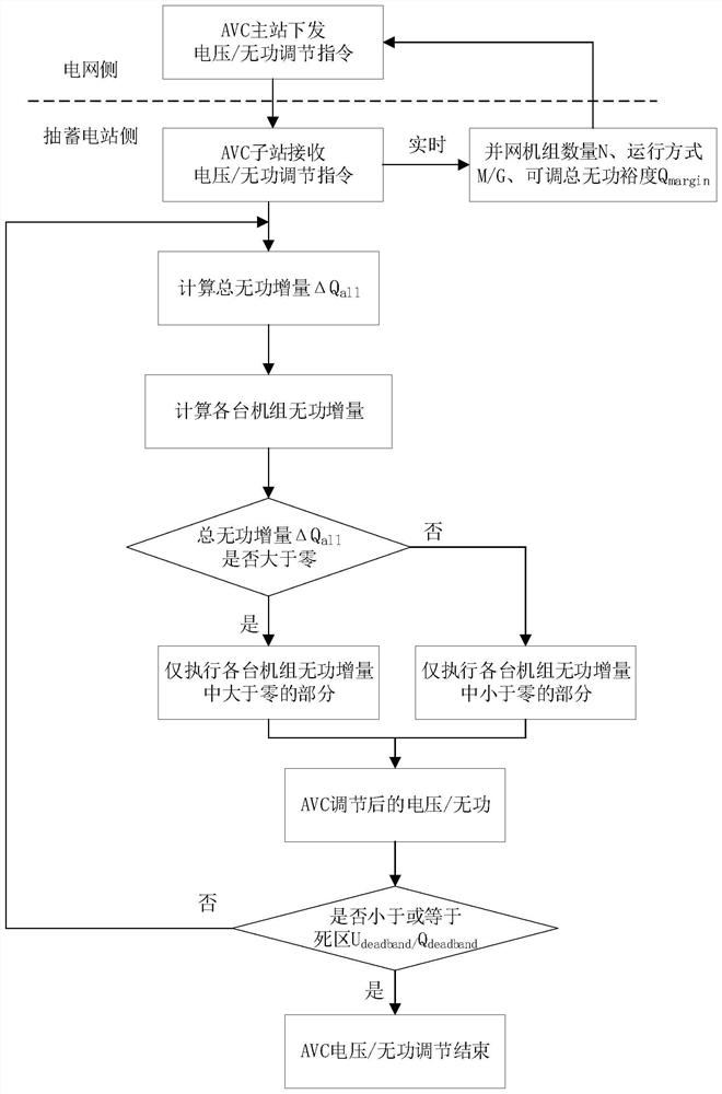
[0040] like figure 1 As shown, a reactive power margin allocation method such as the AVC system of a pumped-storage power station provided by the embodiment of the present invention, the specific steps are as follows:

[0041] Step 1: The AVC master station on the grid side issues a voltage / reactive power adjustment command to the AVC substation of the pumped storage power station;

[0042] A1: In this embodiment, the AVC main station on the grid side sen...


PUM


Abstract

The invention relates to a reactive power margin distribution method for an AVC system. The reactive power margin distribution method balances the reactive power margin of a unit in a pumped storage power station in real time in the AVC adjustment process, and does not need to carry out the reactive power redistribution adjustment of the unit in the station after an adjustment object reaches a target; the reactive power of the units in the station can be reasonably distributed and adjusted under the condition that the reactive power adjustment rates and the reactive power adjustment step lengths of the multiple units in the station are different; and through same-direction judgment, the condition of repeated adjustment when the voltage fluctuates and the target value of the AVC master station is small is avoided. Compared with the prior art, the reactive power margin distribution method has the advantages that reasonable reactive power distribution can be achieved in the mode that the pumped storage power station units run in parallel in multiple working conditions or in different working conditions, and the like.

Description

technical field [0001] The invention relates to a reactive power margin distribution method for an AVC system, in particular. Background technique [0002] The AVC system is a power grid voltage and reactive power control system that operates in an online mode. It collects the bus voltage, bus reactive power, main transformer high and low voltage side reactive power measurement data of each substation and power plant through the dispatching automation SCADA system, as well as the status data of each switch. and other real-time data for online analysis and calculation, and adjust the parameters of various reactive power control equipment in the entire network from the perspective of power grid optimization operation. The existing AVC system has the following characteristics: [0003] 1) At present, in the AVC technology of the power grid, the AVC system of the thermal power plant widely adopts the equal power factor distribution method to operate, and the construction of the ...

Claims


Application Information

Patent Timeline
IPC IPC(8): H02J3/50H02J3/16
CPCH02J3/50H02J3/16Y02E40/30
Inventor 支晓晨李玉齐张健杨帆施宏亮张顺仁延菲
Owner SHANGHAI MINGHUA ELECTRIC POWER TECH & ENG
Learn More