Textile cloth drying equipment

A technology for drying equipment and textile fabrics, applied in progressive dryers, drying chambers/containers, drying solid materials, etc., which can solve the problems of inability to absorb and recycle heat, waste time and resources, and increase the amount of manual labor. The amount of manual labor, the rapid and convenient water discharge, and the effect of reducing heat loss

Active Publication Date: 2021-06-11
湖北新耀实业有限公司
View PDF25 Cites 2 Cited by
  • Summary
  • Abstract
  • Description
  • Claims
  • Application Information

AI Technical Summary

Problems solved by technology

[0005] Aiming at the deficiencies of the prior art, the present invention provides a textile cloth drying equipment, which solves the problem of removing part of the water before drying the textile cloth and then putting it into the drying box. This method has many procedures and increases the amount of manual labor. , time-consuming and laborious, and waste a lot of time and resources, increase production costs, and the drying efficiency is low, which directly affects production efficiency, and the heat cannot be absorbed and recycled, resulting in waste of resources and reducing the use performance.

Method used


Image

  • Textile cloth drying equipment
  • Textile cloth drying equipment
  • Textile cloth drying equipment

Examples


Embodiment example 1

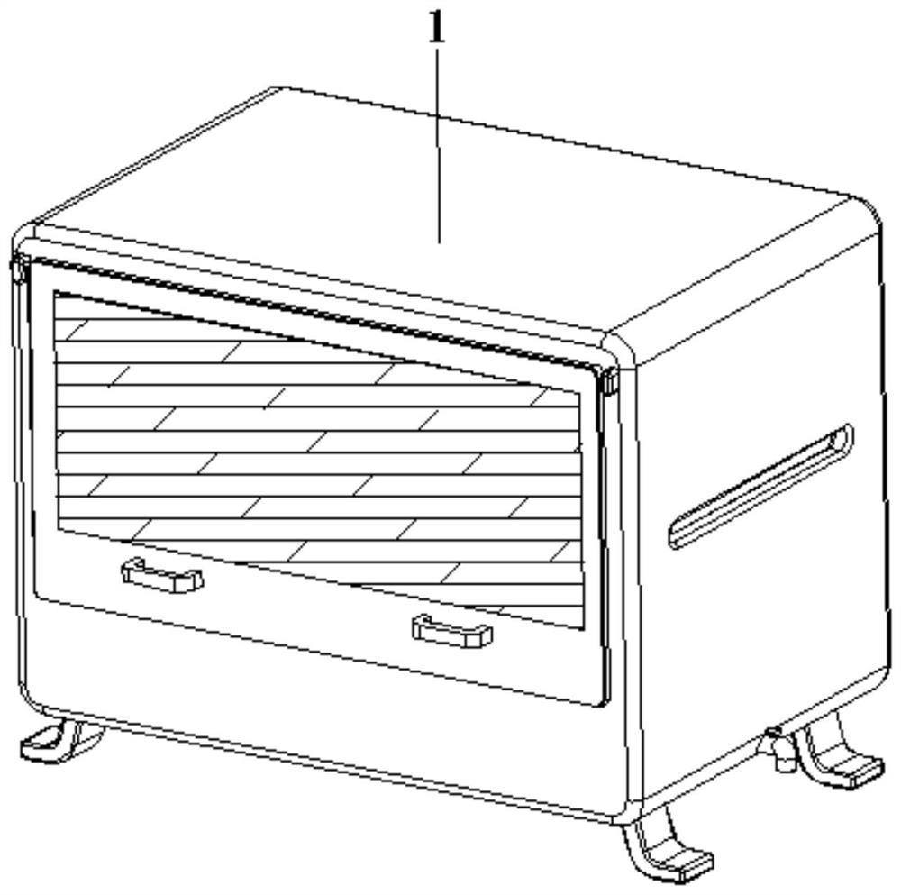
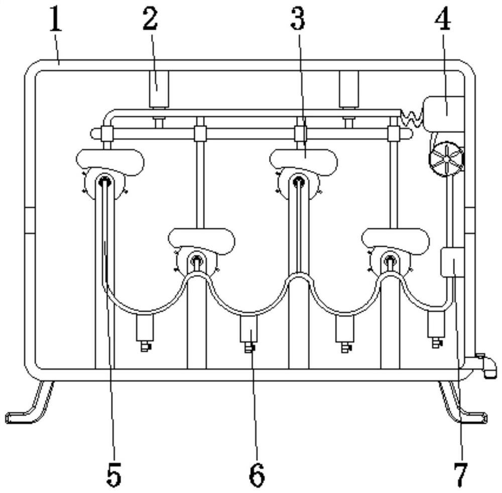
[0033] see Figure 1-7 , the present invention provides a technical solution: a textile cloth drying equipment, including a drying box 1, the interior of the drying box 1 is provided with a lifting mechanism 2, a drying device 3, a heater 4, a curved pipe 5, a water eliminator 6, a gas Dryer 7, lifting mechanism 2 is arranged at the top center of the inner wall of drying box 1, drying device 3 is arranged between the two sides corresponding to the bottom of inner wall of drying box 1 and the bottom of lifting mechanism 2, and heater 4 is fixed on the bottom of drying box 1 On one side of the inner wall and near the top, the outlet end of the heater 4 communicates with the inlet end of the drying device 3 , one end of the curved pipe 5 communicates with the air outlet end of the drying device 3 , and the water eliminator 6 is arranged at the bottom of the curved pipe 5 , The gas drier 7 is fixed on one side of the inner wall of the drying box 1 and near the bottom position, the...

Embodiment example 2

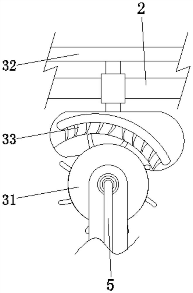
[0039] The drying head device 33 is provided with a base block 331, an arc-shaped gradual change groove 332, and a drying hole 333. The base block 331 is fixed on the bottom end of the connecting pipe 32, and the arc-shaped gradual change groove 332 is provided at the bottom of the base block 331, and the drying hole 333 Opened inside the base block 331 and located at the position of the arc-shaped gradual change groove 332 and communicated with the connecting pipe 32, when the dewatering roller device 31 is rotating, it removes water under the guidance of the arc-shaped gradual change groove 332, At the same time, the cloth will be tightly attached between the base block 331 and the dewatering roller device 31, and the water removal will be further facilitated by extrusion, and the evenly distributed drying holes 333 will output hot drying air to quickly dry the cloth.

[0040] During use, first move the drying head device 33 upwards for an appropriate distance through the lif...


PUM


Abstract

The invention discloses a textile cloth drying equipment. The equipment comprises a drying box, wherein a lifting mechanism is arranged in the center of the top of the inner wall of the drying box, a drying device is arranged among the bottom of the inner wall of the drying box and two corresponding sides of the bottom of the lifting mechanism, a heater is fixed to a position, close to the top, of one side of the inner wall of the drying box, one end of a curve pipe communicates with the air outlet end of the drying device, a gas dryer is fixed to a position, close to the bottom, of one side of the inner wall of the drying box, the air inlet end of the gas dryer communicates with the end, away from the drying device, of the curve pipe, and the air outlet end of the gas dryer communicates with the air inlet end of the heater. The invention relates to the technical field of textile drying. According to the textile cloth drying equipment, purposes of heat cyclic utilization and rapid drying are achieved, moisture can be extruded out in time, auxiliary time is shortened, drying is rapid and convenient, meanwhile, heat can be recycled, heat loss is reduced, and drying efficiency and the performance are improved.

Description

technical field [0001] The invention relates to the technical field of textile drying, in particular to a textile drying equipment. Background technique [0002] The original meaning of textile is taken from the general term of spinning and weaving, but with the continuous development and improvement of the textile knowledge system and subject system, especially after the emergence of non-woven textile materials and three-dimensional composite weaving technologies, textile is not only the traditional spinning and weaving Weaving also includes non-woven technology, three-dimensional weaving technology, electrostatic nano-netting technology, etc. Weaving is roughly divided into two processes: spinning and weaving. After the cloth is woven, it needs to be cleaned by cleaning equipment to remove the wool on the cloth, and then the cloth is dried by the drying equipment. Textile drying equipment refers to a combination of a series of mechanical equipment that dries moisture or ...

Claims


Application Information

Patent Timeline
Patent Type & Authority Applications(China)
IPC IPC(8): F26B13/10F26B13/26F26B13/28F26B21/00F26B25/00F26B25/02F26B25/04F26B25/06
CPCF26B13/28F26B13/26F26B25/02F26B13/08F26B23/00F26B25/00F26B21/001Y02P70/10
Inventor 王婧怡
Owner 湖北新耀实业有限公司
Why Eureka
Try Eureka