
Injector and vehicle

A technology of injectors and injection pipes, applied in fuel injection devices, machines/engines, internal combustion piston engines, etc., can solve the problem that methanol fuel cannot be fully injected, and achieve the effect of shortening the injection distance

Active Publication Date: 2021-06-11
ZHEJIANG GEELY HLDG GRP CO LTD +3
View PDF12 Cites 1 Cited by
  • Summary
  • Abstract
  • Description
  • Claims
  • Application Information

AI Technical Summary

Problems solved by technology

[0007] In order to solve the problem that methanol fuel cannot be fully injected into the combustion chamber in the prior art, the present invention proposes an injector and a vehicle, and the present invention is specifically realized by the following technical scheme

Method used


Image

  • Injector and vehicle

Examples


Embodiment 1

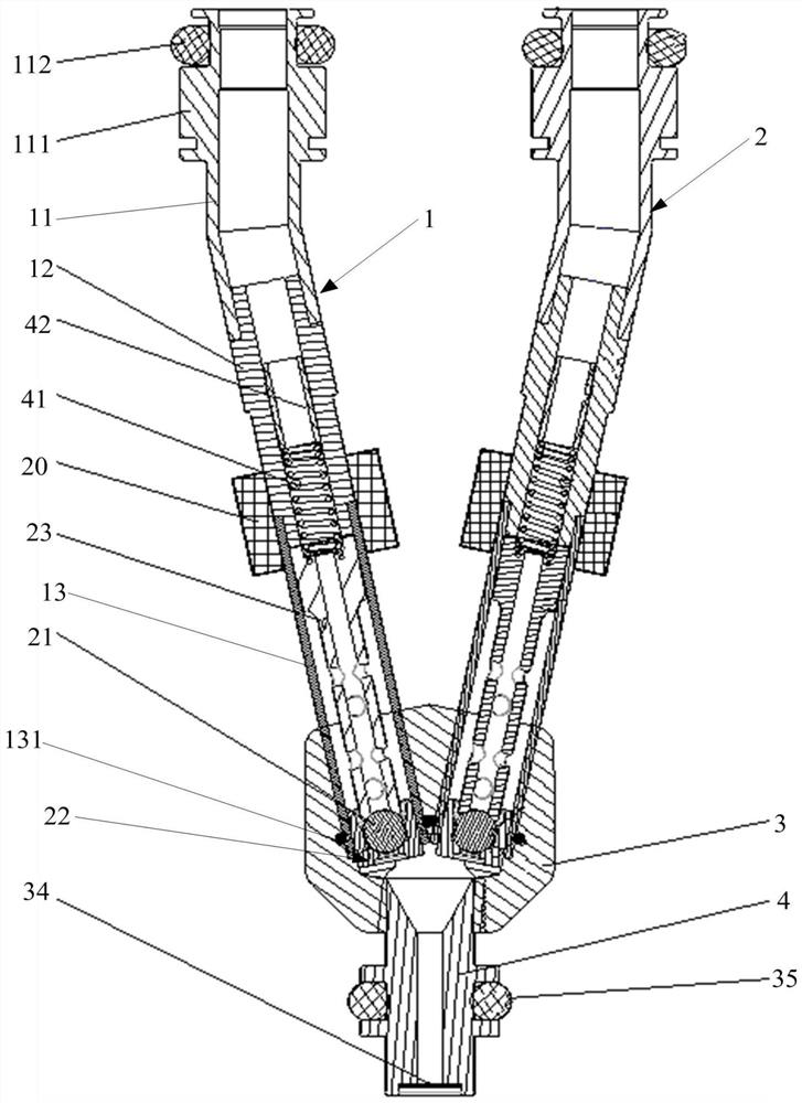
[0029] combine figure 1 As shown, the injector provided by this embodiment 1 includes: a base 3, the base 3 is provided with a first mounting hole and a second mounting hole; a nozzle 4, the nozzle 4 is connected to the base 3, and the nozzle 4 is respectively connected to the first mounting hole and the second mounting hole The two installation holes are connected; the first injection pipe 1, the first injection pipe 1 is located in the first installation hole, the outlet of the first injection pipe 1 communicates with the nozzle 4, and the first injection pipe 1 is used to deliver the first fuel to the nozzle 4 The second injection pipe 2, the second injection pipe 2 is located in the second installation hole, the outlet of the second injection pipe 2 communicates with the nozzle 4, and the second injection pipe 2 is used to deliver the second fuel to the nozzle 4. In this embodiment 1, the first fuel is methanol, and the second fuel is gasoline. The nozzle 4 is used to con...

Embodiment 2

[0052] Embodiment 2 provides a vehicle, including the injector in Embodiment 1 and a control module, the control module is connected to the injector, and the control module is used to control the first injection pipe 1 and the second injection pipe 2 of the injector. The control module in Embodiment 2 can be integrated in the vehicle controller, judge the current demand of the vehicle and control the injector according to the user's operation instruction. In Embodiment 2, the injector can be installed on the cylinder head or the intake pipe of the vehicle.

[0053] In the present invention, the first injection pipe 1 and the second injection pipe 2 are assembled on the base 3 at the same time. When the vehicle uses gasoline, the second injection pipe 2 works to deliver the gasoline to the nozzle 4, and the nozzle 4 passes through the orifice plate , and finally enter the combustion chamber; at this time, the first injection pipe 1 is in a closed state because it is not energiz...


PUM


Abstract

The invention provides an injector and a vehicle so as to solve the problem that in the prior art, methanol fuel cannot be fully injected into a combustion chamber. The injector comprises a base, a nozzle, a first injection pipe and a second injection pipe, wherein the base is provided with a first mounting hole and a second mounting hole; the nozzle is connected with the base and communicated with the first mounting hole and the second mounting hole; the first injection pipe is arranged in the first mounting hole, an outlet of the first injection pipe is communicated with the nozzle, and the first injection pipe is used for conveying methanol to the nozzle; and the second injection pipe is arranged in the second mounting hole, an outlet of the second injection pipe is communicated with the nozzle, and the second injection pipe is used for conveying gasoline to the nozzle. According to the injector, two kinds of fuel injectors are combined into a whole, the first injection pipe and the second injection pipe are connected to the combustion chamber through the base and the nozzle, two kinds of fuel can be injected at the same position, the methanol injection distance is the same as the gasoline injection distance during injection, the methanol injection distance is shortened, and the methanol can be fully injected into the combustion chamber.

Description

technical field [0001] The invention relates to the field of mechanical structures, in particular to an injector and a vehicle. Background technique [0002] At present, the market is vigorously promoting methanol vehicles. The methanol engine needs to run normally, and methanol must be injected into the combustion chamber before it can be burned. As a new type of liquid fuel, methanol has a high ignition point and a large latent heat of vaporization. It needs to absorb a large amount of heat at the beginning of combustion. If the vehicle is cold and injects methanol directly into the combustion chamber, the engine will fail to ignite. [0003] In order to solve the problem that methanol cannot be ignited in a cold car, the vehicle is first ignited with gasoline, and when the temperature of the vehicle rises, methanol is injected into the combustion chamber, and methanol has been continuously used since then. [0004] Current vehicles use two sets of fuel injection systems...

Claims


Application Information

Patent Timeline
Patent Type & Authority Applications(China)
IPC IPC(8): F02M43/04F02M61/16
CPCF02M43/04F02M61/16Y02T10/30
Inventor 李博
Owner ZHEJIANG GEELY HLDG GRP CO LTD
Learn More