Self-unloading and self-weighing multipurpose container with folding top door and doors opening on two sides
A multi-purpose container technology, applied in the field of containers, can solve the problems of long operation time, uneven loading, low operation efficiency, etc., and achieve the effect of reducing loading and unloading costs, improving loading and unloading efficiency, and improving efficiency
- Summary
- Abstract
- Description
- Claims
- Application Information
AI Technical Summary
Problems solved by technology
Method used
Image
Examples
Embodiment 1
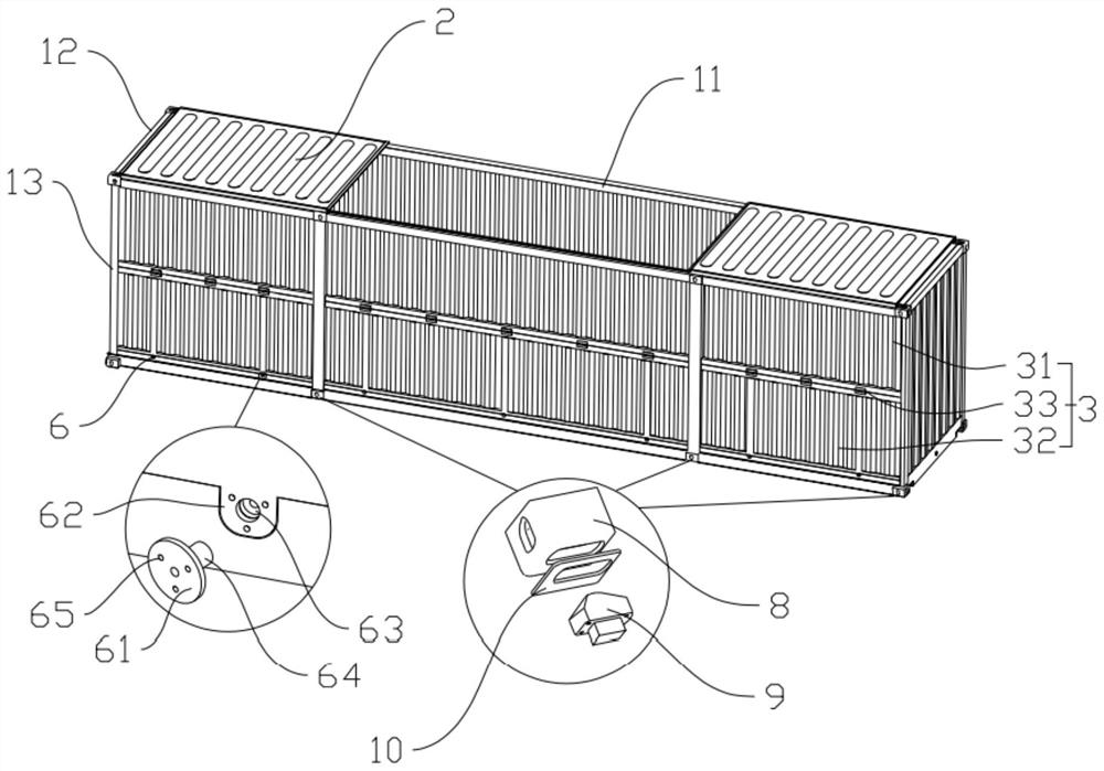
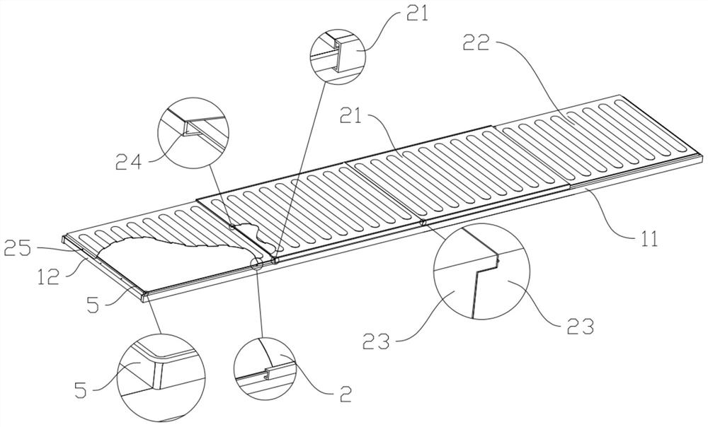
[0042] Such as figure 1 , figure 2 , Figure 7 with Figure 8 As shown, a self-unloading and self-weighing multi-purpose container with doors on both sides of the folding top door includes a frame body 1, the frame body 1 is 20 feet or 40 feet, and the frame body 1 includes longitudinal load-bearing beams 11, transverse Load-bearing beams 12 and vertical load-bearing columns 13, the frame body 1 is provided with a top door assembly 2, a side door assembly 3, and a floor assembly 4, and a rectangular frame-shaped waterproof ring 5 is arranged around the top of the frame body 1. The top door assembly 2 includes a main door 21 and an auxiliary door 22 that equally divide the length of the frame body 1, the auxiliary door 22 is fixedly arranged on the frame main body 1, and the main door 21 is slidably arranged on the outer side of the waterproof ring 5. On the longitudinal load-bearing beam 11, the side of the auxiliary door 22 far away from the main door 21 is fastened to th...
Embodiment 2
[0046] Such as figure 1 with image 3 As shown, the side door assembly 3 includes a fixed upper box panel 31 and a movable lower box panel 32, and the upper side box panel 31 and the lower side box panel 32 respectively account for 1 / 3 of the height of the container. 2. One side of the lower box plate 32 is rotatably connected to the upper box plate 31 , and the other side is provided with a locking structure 6 . A first rotary hinge 33 is arranged between the upper box plate 31 and the lower box plate 32, and the first rotary hinge 33 is arranged at intervals along the longitudinal direction of the load-bearing beam 11; the lock The tight structure 6 includes a stopper pin 61, a locking door nose 62 arranged on the lower side case plate 32, and a limit hole 63 provided on the frame body 1. The center of the stopper pin 61 extends with a The top screw 64 corresponding to the limit hole 63, the screw hole 65 located on the side of the top screw 64 is also opened on the said s...
Embodiment 3
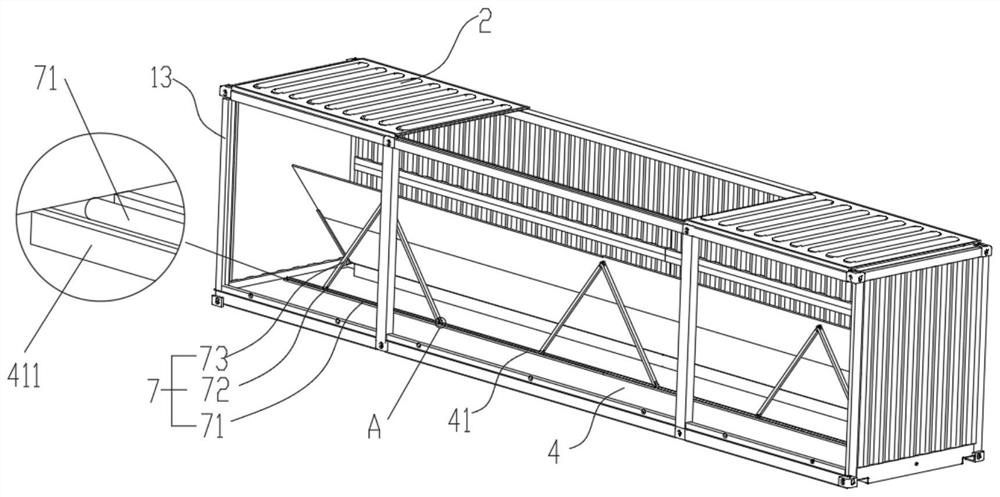
[0050] Such as image 3 with Figure 5 As shown: the bottom plate assembly 4 includes a bottom load-bearing beam 41 arranged parallel to the longitudinal load-bearing beam 11, the bottom load-bearing beam 41 is located in the middle of the transverse load-bearing beam 12, and the bottom load-bearing beam 41 has a The groove 411 extending in the length direction, the two sides of the bottom load-bearing beam 41 are provided with a left self-unloading main floor 42 and a right self-unloading main floor 43, and the left self-unloading main floor 42 and the right self-unloading main floor 43 are far away from all One side of the bottom load-bearing beam 41 is rotatably connected to the frame body 1, and the end faces of the left self-unloading main floor 42 and the right self-unloading main floor 43 are respectively provided with guide chute 44, and inside the guide chute 44 The corresponding left self-unloading lifting sub-base plate 45 and the right self-unloading lifting sub-b...
PUM
 Abstract
Description
Claims
Application Information
 - R&D
- Intellectual Property
- Life Sciences
- Materials
- Tech Scout
- Unparalleled Data Quality
- Higher Quality Content
- 60% Fewer Hallucinations
Browse by: Latest US Patents, China's latest patents, Technical Efficacy Thesaurus, Application Domain, Technology Topic, Popular Technical Reports.
© 2025 PatSnap. All rights reserved.Legal|Privacy policy|Modern Slavery Act Transparency Statement|Sitemap|About US| Contact US: help@patsnap.com


