
Steel wire gluing structure for tire

A steel wire and tire technology, applied in the direction of pretreatment surface, device for coating liquid on the surface, coating, etc., can solve the problems of uneven distribution of rubber, affecting the use effect of steel wire, etc., to achieve reduced leakage, consistent diameter, and easy use Effect

Active Publication Date: 2021-06-11
重庆市九龙橡胶制品制造有限公司
View PDF15 Cites 0 Cited by
  • Summary
  • Abstract
  • Description
  • Claims
  • Application Information

AI Technical Summary

Problems solved by technology

[0004] The present invention intends to provide a steel wire gluing structure for tires, to solve the prior art by coating rubber on the opposite side of the upper rubber block and the lower rubber block, and then coating the steel wire from the upper rubbe

Method used


Image

  • Steel wire gluing structure for tire
  • Steel wire gluing structure for tire
  • Steel wire gluing structure for tire

Examples


Embodiment 1

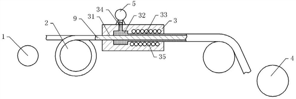
[0034] Steel wire gluing structure for tires, basically as attached figure 1 As shown, including the frame, the frame is provided with an unwinding roller 1, a glue part and a winding roller 4 in sequence from left to right, and the unwinding roller 1 and the winding roller 4 are all rotatably connected on the frame, and the frame Also fixed on the top is a driving member that drives the winding roller 4 to rotate. In this embodiment, the driving member is a winding motor fixed on the frame, and the winding roller 4 is coaxially fixed on the output shaft of the winding motor. The auxiliary roller 2 is rotatably connected between the unwinding roller 1 and the glued part and between the winding roller 4 and the glued part on the frame; two auxiliary motors are also fixed on the frame, and the two auxiliary rollers 2 are respectively The coaxial is fixed on the output shaft of the auxiliary motor.

[0035] The gluing part includes a gluing block 3 fixed on the frame. The gluing...


PUM


Abstract

The invention belongs to the technical field of coating a rubber layer outside a steel wire, and discloses a steel wire gluing structure for a tire. The structure comprises an unwinding roller, a gluing piece and a winding roller which are arranged in sequence, and the structure further comprises a driving piece for driving the winding roller to rotate; the gluing piece comprises a gluing block, a guide-in hole, a gluing hole and a guide-out hole which are coaxial are sequentially formed in the gluing block in the direction facing the winding roller, the diameter of the guide-out hole is larger than that of the guide-in hole, and the diameter of the gluing hole is larger than that of the guide-out hole; a glue inlet hole which communicates with the gluing hole is further formed above the gluing block, and an extrusion piece which communicates with a glue inlet hole is further fixed on the gluing block; and a limiting ring is arranged at one end, communicates with the gluing hole, of the guide-in hole, and a rubber ring is arranged on the inner wall of the limiting ring. The problems that in the prior art, the opposite sides of an upper gluing block and a lower gluing block are coated with rubber, then a steel wire penetrates through the space between the upper gluing block and the lower gluing block to complete gluing, the rubber is prone to being unevenly distributed on the outer wall of the steel wire, and the using effect of the steel wire on a tire is affected are solved.

Description

technical field [0001] The invention belongs to the technical field of covering rubber layers on steel wires, and in particular relates to a steel wire gluing structure for tires. Background technique [0002] The inner ring of the tire is usually equipped with a steel bead, which acts as a radial constraint on the ply of the tire carcass through the steel bead, and the strength of the tire can be enhanced after the bead is installed on the inner ring of the tire. The steel traveler for tires is formed by winding a steel wire into a set number of turns and then bonding it. Before the steel wire for making the traveler is wound, a layer of rubber needs to be wrapped around the steel wire to reduce the probability of the relative friction between the steel wire and the carcass of the tire during use, causing the carcass to be worn out. [0003] The currently used gluing structure includes an upper rubber block and a lower rubber block, rubber is applied on the opposite side o...

Claims


Application Information

Patent Timeline
IPC IPC(8): B05C5/02B05C5/00B05C9/14B05C11/10B05C11/11B05C13/02B05D3/04
CPCB05C5/0241B05C5/001B05C9/14B05C13/02B05C11/10B05C11/11B05D3/0426
Inventor 龙华文申统宇
Owner 重庆市九龙橡胶制品制造有限公司
Learn More