Lifting installation frame for electronic transformer based on multi-leg support

An electronic transformer, lift-type technology, applied in the direction of transformer/reactor installation/support/suspension, etc., can solve the problems of inconvenient adjustment of the height of the electronic transformer by the mounting frame, easy toppling and damage of the electronic transformer, and limitation of the height of the electronic transformer. Follow-up installation, strong practicability, and the effect of improving stability

Active Publication Date: 2022-04-29
天长市超威电子有限公司
View PDF13 Cites 0 Cited by
  • Summary
  • Abstract
  • Description
  • Claims
  • Application Information

AI Technical Summary

Problems solved by technology

[0002] An electronic transformer is an electronic device that converts the AC voltage of the mains into DC and then forms a high-frequency AC voltage output through semiconductor switching devices, electronic components and high-frequency transformer windings. It is also an electronic device described in electronics theory. In this kind of AC / DC inverter circuit, when the electronic transformer is installed and fixed on the ground, it is necessary to support the electronic transformer with the help of a mounting frame to prevent the bottom of the electronic transformer from contacting the ground with moisture and damage. However, the current electronic transformer mounting frame is not stable enough, and four supports are often used The electronic transformer is supported by columns, which makes the electronic transformer easy to fall and damage, and the current mounting frame is inconvenient to adjust the height of the electronic transformer, which limits the installation height of the electronic transformer and lacks practicability. In view of this, we propose an electronic transformer based on multi-leg support With lift mount

Method used


Image

  • Lifting installation frame for electronic transformer based on multi-leg support
  • Lifting installation frame for electronic transformer based on multi-leg support
  • Lifting installation frame for electronic transformer based on multi-leg support

Examples


Embodiment 1

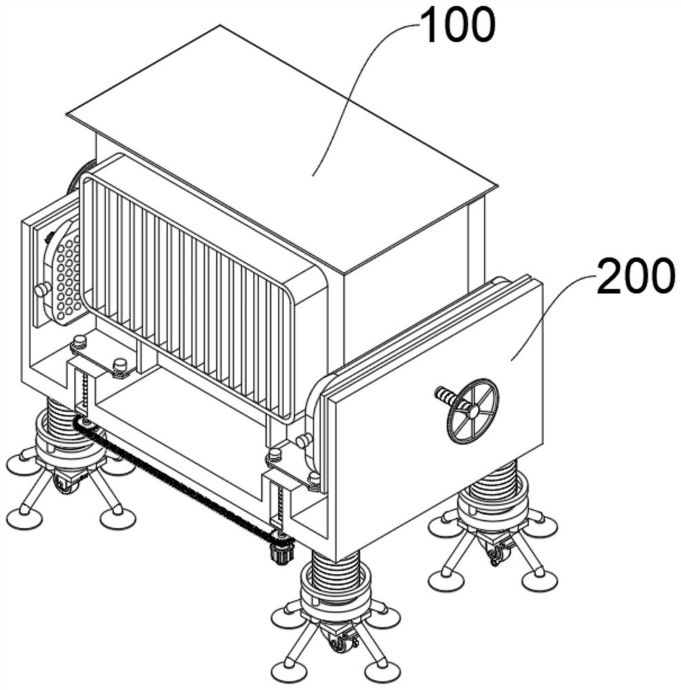
[0040] see Figure 1-Figure 10 As shown, the present embodiment provides an elevating installation frame for electronic transformers based on multi-leg support, including an electronic transformer body 100 and an elevating installation mechanism 200 at the bottom of the electronic transformer body 100. The elevating installation mechanism 200 includes at least:

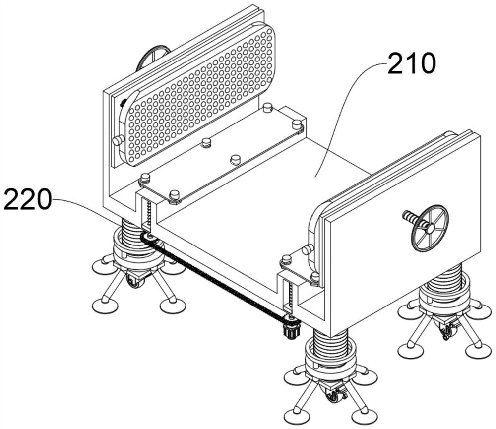
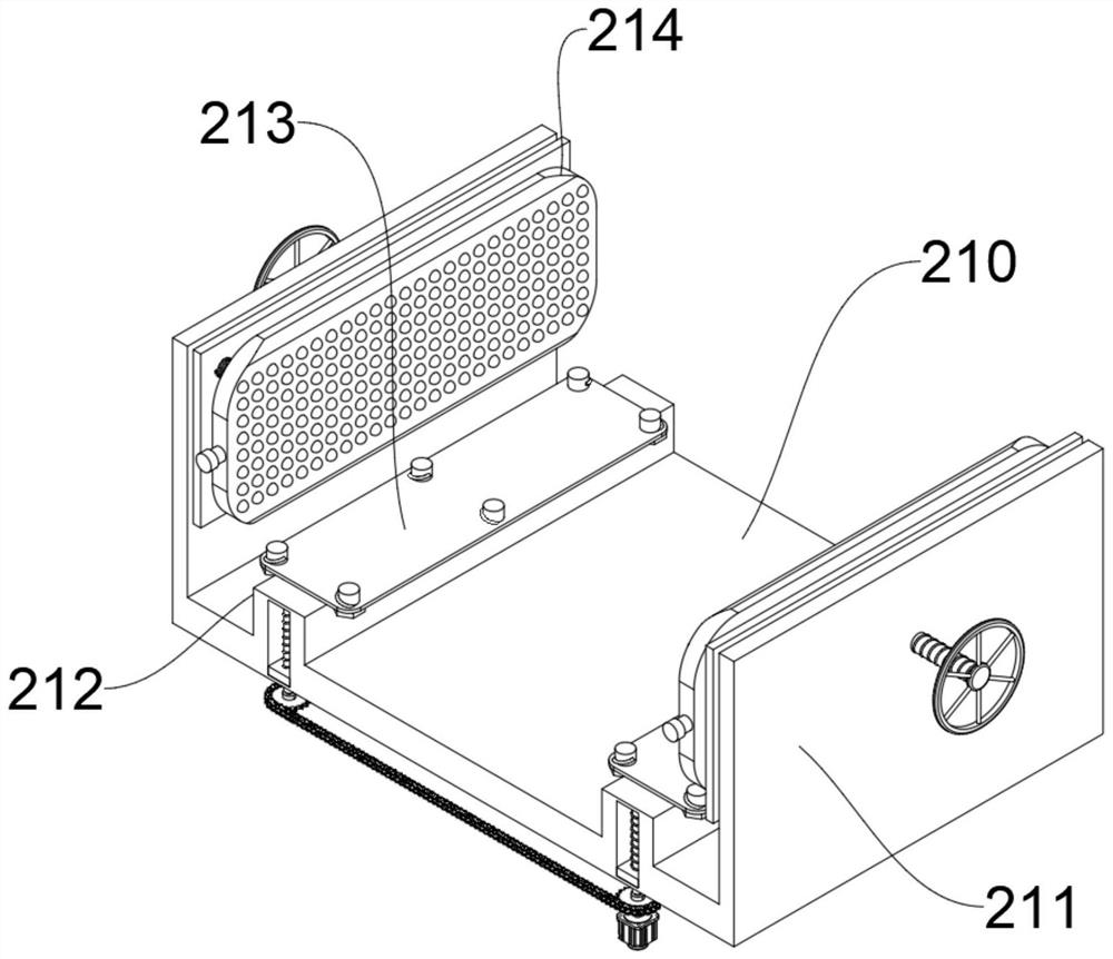
[0041] Connecting the base plate 210, the top of the connecting base plate 210 is provided with two bumps 212, the top of the bumps 212 is provided with a lifting block 213, and the top of the lifting block 213 is provided with a mounting plate 2131, and the mounting plate 2131 is used to thread the electronic transformer body 100 through bolts, The connection between the connection base plate 210 and the electronic transformer body 100 is fixed to ensure the structural integrity, so that the two bumps 212 support the electronic transformer body 100 above the connection base plate 210, so as to prevent the bottom of th...


PUM


Abstract

The invention relates to the technical field of installation of electronic transformers, in particular to an elevating installation frame for electronic transformers based on multi-leg support. It includes the electronic transformer body and the lifting installation mechanism at the bottom of the electronic transformer body. The lifting installation mechanism at least includes: a connecting base plate, two bumps are arranged on the top of the connecting base plate, a lifting block is arranged on the top of the bump, and a mounting plate is arranged on the top of the lifting block. The mounting plate is used to connect the electronic transformer body through bolts and threads. Both ends of the connecting bottom plate are provided with side plates, and the electronic transformer body is located between the two side plates; the supporting device includes supporting legs, and the ends of the four supporting legs are respectively fixed. Connected to the bottom of the connecting base plate near the four corners, the outer wall of the supporting leg is provided with a threaded sleeve, the bottom of the threaded sleeve is connected with a plurality of inclined rods, and the end of the inclined rod is connected with a rubber suction cup. The invention can stably support the electronic transformer at multiple points and is convenient for adjustment. The height at which the electronic transformer is installed.

Description

technical field [0001] The invention relates to the technical field of installation of electronic transformers, in particular to an elevating installation frame for electronic transformers based on multi-leg support. Background technique [0002] An electronic transformer is an electronic device that converts the AC voltage of the mains into DC and then forms a high-frequency AC voltage output through semiconductor switching devices, electronic components and high-frequency transformer windings. It is also an electronic device described in electronics theory. In this kind of AC / DC inverter circuit, when the electronic transformer is installed and fixed on the ground, it is necessary to support the electronic transformer with the help of a mounting frame to prevent the bottom of the electronic transformer from contacting the ground with moisture and damage. However, the current electronic transformer mounting frame is not stable enough, and four supports are often used The el...

Claims


Application Information

Patent Timeline
Patent Type & Authority Patents(China)
IPC IPC(8): H01F27/06
CPCH01F27/06
Inventor 王伟
Owner 天长市超威电子有限公司
Why Eureka
Try Eureka