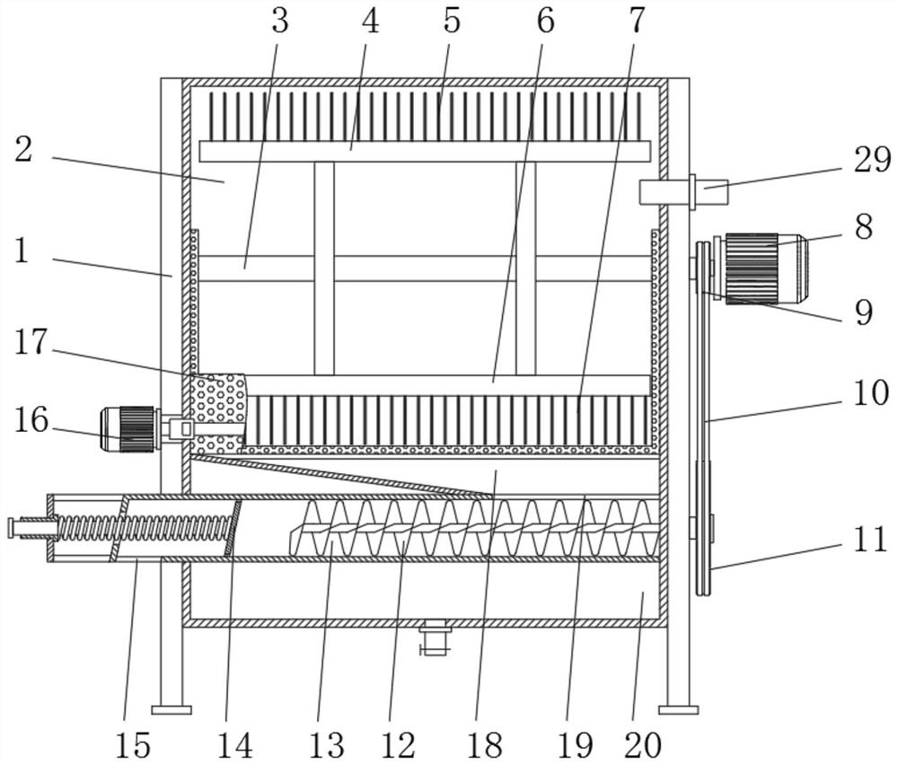
Pure natural plant dye extraction device for garment processing
A technology of natural plant dye and extraction device, which is applied in the field of pure natural plant dye extraction device for garment processing, can solve the problems of low extraction efficiency and high labor intensity, and achieve the effects of improving utilization rate, reducing labor intensity and improving production efficiency.
- Summary
- Abstract
- Description
- Claims
- Application Information
AI Technical Summary
Problems solved by technology
Method used
Image
Examples
Embodiment 1
[0033] Embodiment one, with reference to Figure 1-2 , a pure natural plant dye extraction device for garment processing, comprising a device body 1, a crushing cylinder 2 is arranged above the interior of the device body 1, and a crushing motor 8 is installed on one side of the crushing cylinder 2 on the surface of the device body 1 through a bracket 30, and The top of the pulverizing motor 8 is located at the side of the device body 1 and is provided with a water inlet 29. A small pulley 9 is installed on the output shaft of the pulverizing motor 8, and is connected to the drive shaft 3 installed in the inside of the pulverizing cylinder 2 through a coupling. The drive shaft 3 An upper knife rest 4 and a lower knife rest 6 are welded on the top, and an upper cutter 5 and a lower cutter 7 are installed on the top surface of the upper knife rest 4 and the bottom surface of the lower knife rest 6 respectively. A filter hopper 17, and the bottom of the filter hopper 17 is provid...
Embodiment 2
[0034] Embodiment two, refer to Figure 1-4 , the filter bucket 17 is welded by two fan-shaped vertical plates 17.1 and an arc-shaped bottom plate 17.2, and the surfaces of the vertical plate 17.1 and the bottom plate 17.2 are provided with filter holes, and the bottom surface of the bottom plate 17.2 is equipped with an overturning chain 24 through a fixed block 25, And the bottom of the overturning chain 24 is meshed with a sprocket 23, the sprocket 23 is installed on the overturning shaft 27, and one end of the overturning shaft 27 extends to the side of the device body 1 and is connected with the overturning motor 16 through a coupling, the overturning chain 24 and the sprocket 23 There are two respectively, and two turning chains 24 and two sprockets 23 are distributed symmetrically about the vertical center line of the filter bucket 17. The filter bucket 17 set in the crushing cylinder 2 has a turning function. When discharging slag, the turning motor 16 drives the turni...
Embodiment 3
[0035] Embodiment three, refer to figure 1 with image 3 , the spiral tube 13 is a circular tube structure, and the upper surface of the spiral tube 13 is provided with a feed port 19, and the lower surface is located on the side of the device body 1 and is provided with a slag discharge port 15, and the lower surface of the spiral tube 13 is located inside the device body 1 A filter hole is provided, one side of the spiral tube 13 is provided with a screw conveying paddle 12, and one side of the screw conveying paddle 12 is provided with an extruding plate 14, and the surface of one side of the extruding plate 14 is connected with the guide rod 22, and the guide rod 22 is connected with the guide rod 22. One end of the spiral tube 13 is slidingly connected through the guide sleeve 31 installed on the bracket 30, and one end of the screw conveyor paddle 12 extends to the side of the device body 1 to connect with the large pulley 11, and the large pulley 11 is connected to the ...
PUM
 Abstract
Description
Claims
Application Information
 - R&D
- Intellectual Property
- Life Sciences
- Materials
- Tech Scout
- Unparalleled Data Quality
- Higher Quality Content
- 60% Fewer Hallucinations
Browse by: Latest US Patents, China's latest patents, Technical Efficacy Thesaurus, Application Domain, Technology Topic, Popular Technical Reports.
© 2025 PatSnap. All rights reserved.Legal|Privacy policy|Modern Slavery Act Transparency Statement|Sitemap|About US| Contact US: help@patsnap.com


