
Pedal type swimming boosting device

A pedal-type, booster technology, applied in swimming, swimming frame, sports accessories, etc., can solve the problems of not feeling the fun of swimming, drowning, working hours, etc.

Pending Publication Date: 2021-06-08
井文贵
View PDF0 Cites 0 Cited by
  • Summary
  • Abstract
  • Description
  • Claims
  • Application Information

AI Technical Summary

Problems solved by technology

[0003] For swimming enthusiasts, swimming and playing in the water is a kind of exercise and a very interesting thing. It is a favorite sport for most people, but it consumes a lot of energy. For most people, their physical strength cannot keep up. , there is a danger of drowning if you stay in the water for a long time
[0004] However, swimming requires a certain skill, which is not something that ordinary people can do. Those who can't have to use other tools to do it.
Now generally all rely on life-saving tools, using life-saving tools is not only difficult to learn to swim, but also can not feel the real fun of swimming
At the same time, for people who can swim, in order to increase their swimming speed, they generally use auxiliary tools such as flippers or electric propellers, but the use of flippers cannot improve the faster speed, and the cost of electric propellers is too expensive, not for ordinary swimmers. can bear
[0005] At the same time, another disadvantage of electric propulsion is that it uses battery power supply for power supply, and the battery has potential safety hazards in the water. In addition, due to the limitation of battery technology, the working time of this type of propeller is relatively short, and the market product logo can last up to 50 years. minutes, but after a period of use, the actual use is mostly 20 to 30 minutes, and the same price is thousands or thousands of yuan

Method used


Image

  • Pedal type swimming boosting device
  • Pedal type swimming boosting device
  • Pedal type swimming boosting device

Examples


Embodiment 1

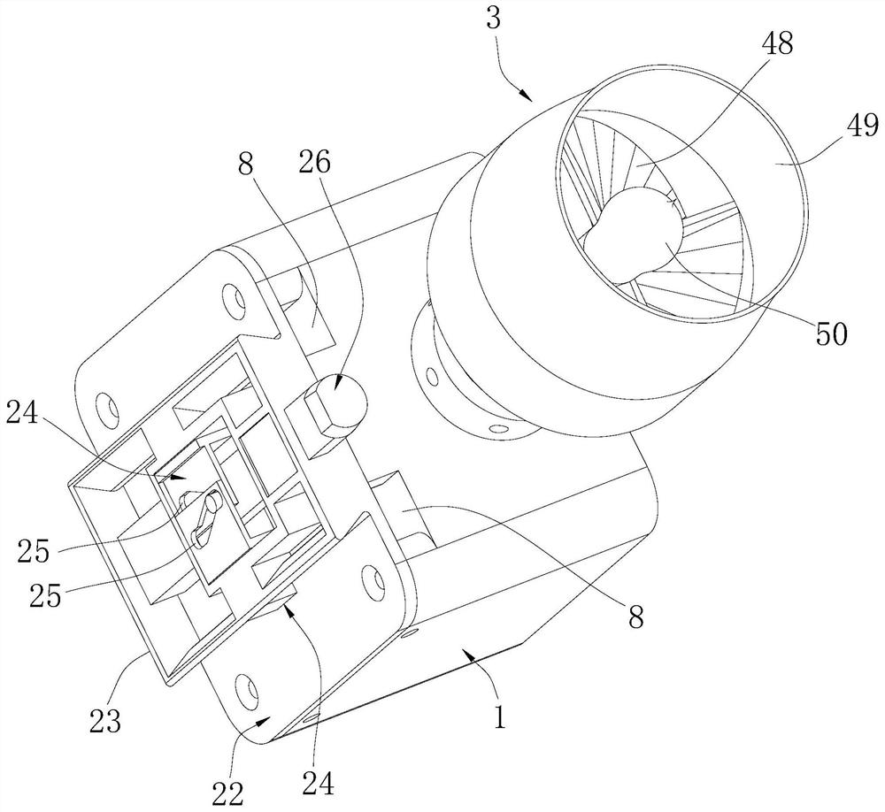
[0038] A foot-operated swimming booster, comprising a housing 1, a rotatable main shaft 2 is arranged in the housing 1, one end of the main shaft 2 protrudes from the housing 1, and an impeller 3 is arranged at the end of the protruding direction. A rotatable sprocket 4 is arranged on the outside of the body 1, and a main bevel gear 5 is connected to the sprocket 4 in the housing 1, and a slave bevel gear 6 that is in transmission engagement with the main bevel gear 5 is arranged on the main shaft 2 When in use, the device of the present invention is placed in water, and the sprocket 4 is rotated, and the sprocket 4 drives the main bevel gear 5 to rotate and drives the slave bevel gear 6 to drive the main shaft 2 to rotate, and the main shaft rotates to make the impeller rotate, and the impeller Rotate to push the device forward. Wherein the sprocket 4 can be directly connected to the main bevel gear through the transmission shaft to realize the transmission connection.

[0039...

Embodiment 2

[0043] A foot-operated swimming booster, comprising a housing 1, a rotatable main shaft 2 is arranged in the housing 1, one end of the main shaft 2 protrudes from the housing 1, and an impeller 3 is arranged at the end of the protruding direction. A rotatable sprocket 4 is arranged on the outside of the body 1, and a main bevel gear 5 is connected to the sprocket 4 in the housing 1, and a slave bevel gear 6 that is in transmission engagement with the main bevel gear 5 is arranged on the main shaft 2 , rotate the sprocket 4, the sprocket 4 drives the main bevel gear 5 to rotate and drives the slave bevel gear 6 to drive the main shaft 2 to rotate. That is, rotating the sprocket 4 can realize driving the impeller 3 to rotate to generate propulsion in water.

[0044] In order to improve the transmission ratio between the sprocket 4 and the impeller 3, the speed of rotation of the impeller 3 is improved under the condition that the sprocket 4 rotates at a certain speed, so as to o...

Embodiment 3

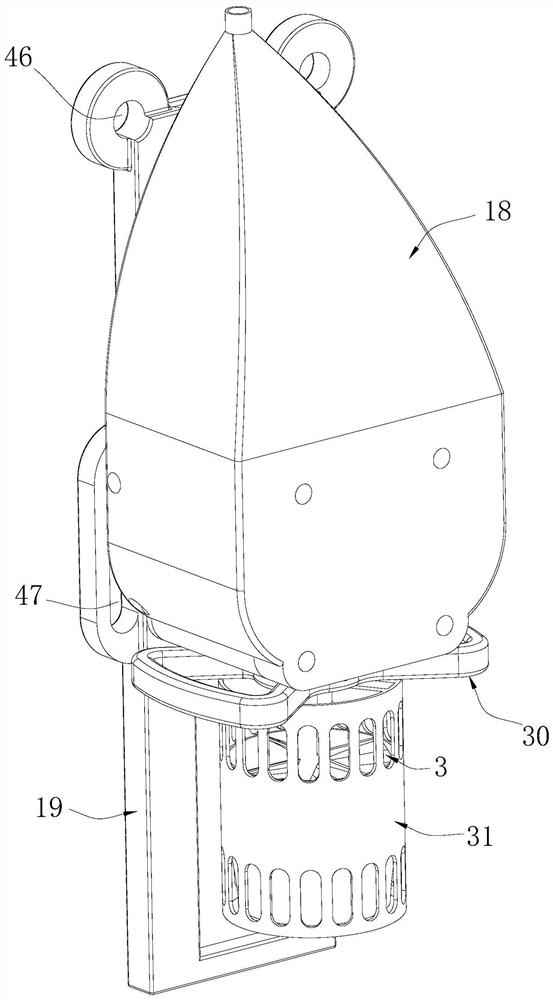
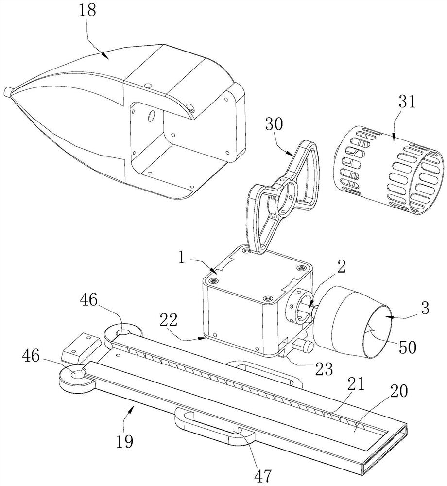
[0053] A foot-operated swimming booster, comprising a housing 1, a rotatable main shaft 2 is arranged in the housing 1, one end of the main shaft 2 protrudes from the housing 1, and an impeller 3 is arranged at the end of the protruding direction. A rotatable sprocket 4 is arranged on the outside of the body 1, and a main bevel gear 5 is connected to the sprocket 4 in the housing 1, and a slave bevel gear 6 that is in transmission engagement with the main bevel gear 5 is arranged on the main shaft 2 , rotate the sprocket 4, the sprocket 4 drives the main bevel gear 5 to rotate and drives the slave bevel gear 6 to drive the main shaft 2 to rotate. That is, rotating the sprocket 4 can realize driving the impeller 3 to rotate to generate propulsion in water. Also includes a leading cone 18, the leading cone 18 is fixedly connected to the side of the housing 1 away from the direction of the impeller 3, and the end of the leading cone 18 away from the direction of the impeller 3 is...


PUM


Abstract

The invention discloses a pedal type swimming boosting device. The pedal type swimming boosting device comprises a shell; a rotatable main shaft is arranged in the shell; one end of the main shaft extends out of the shell; an impeller is arranged at the extending direction end of the main shaft; a rotatable chain wheel is arranged on the outer side of the shell; a master bevel gear is arranged in the shell and connected with the chain wheel; the main shaft is provided with a slave bevel gear in transmission engagement with the master bevel gear, and a rotating chain wheel; and the chain wheel drives the master bevel gear to rotate so as to drive the slave bevel gear to drive the main shaft to rotate. According to the pedal type swimming boosting device, manual power can be adopted, the effects of exercising the body and improving the swimming experience can be better achieved, the swimming advancing speed is increased, and meanwhile the problem of continuous use limitation does not exist.

Description

technical field [0001] The invention relates to a swimming booster, in particular to a foot-operated swimming booster. Background technique [0002] Swimming is a kind of sports that most people like, especially in the hot summer, if you can take a dip in the swimming pool or the river, you can not only prevent heatstroke and cool down, but also exercise your body. At the same time, you can also feel the benefits of swimming. pleasure. [0003] For swimming enthusiasts, swimming and playing in the water is a kind of exercise and a very interesting thing. It is a favorite sport for most people, but it consumes a lot of energy. For most people, their physical strength cannot keep up. , There is a risk of drowning if you stay in the water for a long time. [0004] However, swimming requires a certain skill, which is not something that most people can do. Those who don't know how to swim must use other tools to do it. Generally all are by means of life-saving tool now, utiliz...

Claims


Application Information

Patent Timeline
Patent Type & Authority Applications(China)
IPC IPC(8): A63B35/10
CPCA63B35/10
Inventor 井文贵
Owner 井文贵
Learn More