
Double-frequency-point ultrahigh-frequency broadband tag antenna

A tag antenna and ultra-high frequency technology, which is applied in the field of dual-frequency ultra-high frequency broadband tag antennas, can solve the problems of radio frequency identification system application field limitations, narrow working frequency band coverage of tag antennas, and unrecognizable tags.

Pending Publication Date: 2021-06-04
NINGBO UNIV
View PDF18 Cites 2 Cited by
  • Summary
  • Abstract
  • Description
  • Claims
  • Application Information

AI Technical Summary

Problems solved by technology

[0005] Most of the existing tag antennas are designed based on the working frequency band of one or two countries in the ultra-high frequency band. The working frequency band coverage of this kind of tag antenna is narrow, which leads to the limitation of the application field of radio frequency identification system
For example, when the radio frequency identification system is used in temperature sensing, logistics and supply chain management, since different items are labeled with different labels, the number of labels is large and the distance between the labels will be very close. The tag antennas are located in the near-field radiation area of ​​each other, which will inevitably interfere with each other, which will cause the frequency point of the tag antenna to shift left and right and deviate from its designed working frequency band, resulting in many tags not being recognized by the reader

Method used


Image

  • Double-frequency-point ultrahigh-frequency broadband tag antenna
  • Double-frequency-point ultrahigh-frequency broadband tag antenna
  • Double-frequency-point ultrahigh-frequency broadband tag antenna

Examples


Embodiment

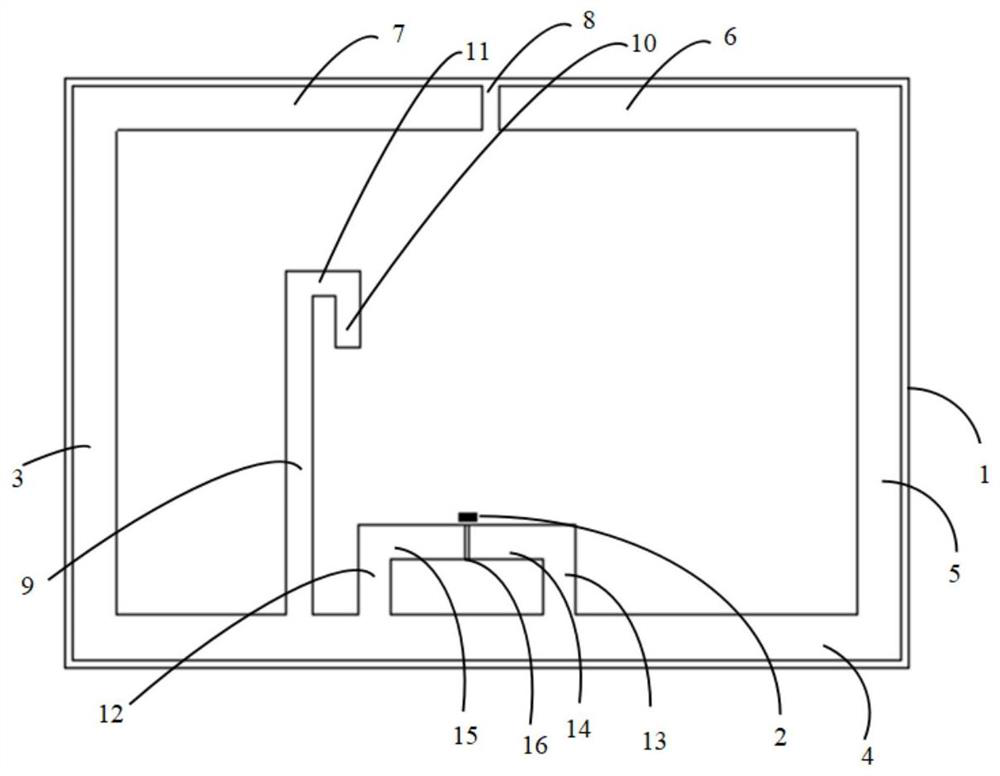
[0017] Example: such as figure 1As shown, a dual-frequency UHF broadband tag antenna includes a dielectric substrate 1, a resonant structure, an impedance matching structure and a metal pad 2, the resonant structure includes a first resonant unit and a second resonant unit, and the first resonant unit and The second resonance unit is used to generate high and low resonance frequency points. The first resonance unit includes the first rectangular metal microstrip line 3 attached to the upper surface of the dielectric substrate 1, the second rectangular metal microstrip line 4, and the third rectangular metal microstrip line. The strip line 5, the fourth rectangular metal microstrip line 6 and the fifth rectangular metal microstrip line 7, the first rectangular metal microstrip line 3 parallel to the third rectangular metal microstrip line 5, the fourth rectangular metal microstrip line 6 and The fifth rectangular metal microstrip line 7 is parallel to the second rectangular met...


PUM

PropertyMeasurementUnit
Thicknessaaaaaaaaaa
Lengthaaaaaaaaaa
Widthaaaaaaaaaa

Abstract

The invention discloses a double-frequency-point ultrahigh-frequency broadband tag antenna, which comprises a dielectric substrate, a resonant structure, an impedance matching structure and a metal bonding pad, and is characterized in that the resonant structure comprises a first resonant unit and a second resonant unit; the first resonance unit comprises a first rectangular metal microstrip line, a second rectangular metal microstrip line, a third rectangular metal microstrip line, a fourth rectangular metal microstrip line and a fifth rectangular metal microstrip line which are attached to the upper surface of the dielectric substrate; the second resonance unit comprises a sixth rectangular metal microstrip line, a seventh rectangular metal microstrip line and an eighth rectangular metal microstrip line which are attached to the upper surface of the dielectric substrate, and the impedance matching structure is located on the front side of the second rectangular metal microstrip line and located on the right side of the second resonance unit. The impedance matching structure comprises a ninth rectangular metal microstrip line, a tenth rectangular metal microstrip line, an eleventh rectangular metal microstrip line and a twelfth rectangular metal microstrip line which are attached to the upper surface of the dielectric substrate; and the antenna has the advantage of wide working frequency range coverage.

Description

technical field [0001] The invention relates to a tag antenna, in particular to a dual-frequency point ultra-high frequency broadband tag antenna. Background technique [0002] Radio Frequency Identification (RFID, Radio Frequency Identification) technology is a non-contact automatic identification technology. It relies on radio frequency signals to automatically identify target objects and obtain corresponding data. The identification work is automatic and does not require manual intervention. It can work in various in different environments. Due to its wide applicability and high reading and writing speed, RFID technology has been widely used in many industries and fields. [0003] The current radio frequency identification system implemented by radio frequency identification technology is mainly composed of three parts: a reader, a label, and a data exchange and management system. The reader is a device for reading label information, and the label mainly includes a label...

Claims


Application Information

Patent Timeline
IPC IPC(8): H01Q1/38H01Q1/22H01Q5/10
CPCH01Q1/38H01Q1/2225H01Q5/10
Inventor 华昌洲周晔晔黄雪琴陈益叶旭超
Owner NINGBO UNIV
Learn More