LBF-Based Detection Method for Satellite Telescope Lens Surface Defects

A detection method and telescope technology, applied in the direction of optical defect/defect, image analysis, image enhancement, etc., can solve the size limit of detection optical components, complex equipment assembly, in-situ non-contact defect detection of large-scale optical devices, etc. problem, to achieve the effect of reducing running time and improving convergence speed

Active Publication Date: 2022-04-19
UNIV OF ELECTRONICS SCI & TECH OF CHINA
View PDF5 Cites 0 Cited by
  • Summary
  • Abstract
  • Description
  • Claims
  • Application Information

AI Technical Summary

Problems solved by technology

For the traditional precision system for detecting surface defects, although the detection accuracy is high, the equipment assembly is complicated and the cost is high, and there are strict requirements on the positional relationship and movement of the components. If the specific posture changes, the The directional indication also changes accordingly, so the operator is required to have a certain knowledge base of the optical neighborhood
The biggest disadvantage of the precision system is that the size of the detection optical components is limited. The measured objects are usually in the order of centimeters or decimeters, and it is impossible to perform in-situ non-contact defect detection on large-size optical components.

Method used


Image

  • LBF-Based Detection Method for Satellite Telescope Lens Surface Defects
  • LBF-Based Detection Method for Satellite Telescope Lens Surface Defects
  • LBF-Based Detection Method for Satellite Telescope Lens Surface Defects

Examples


example

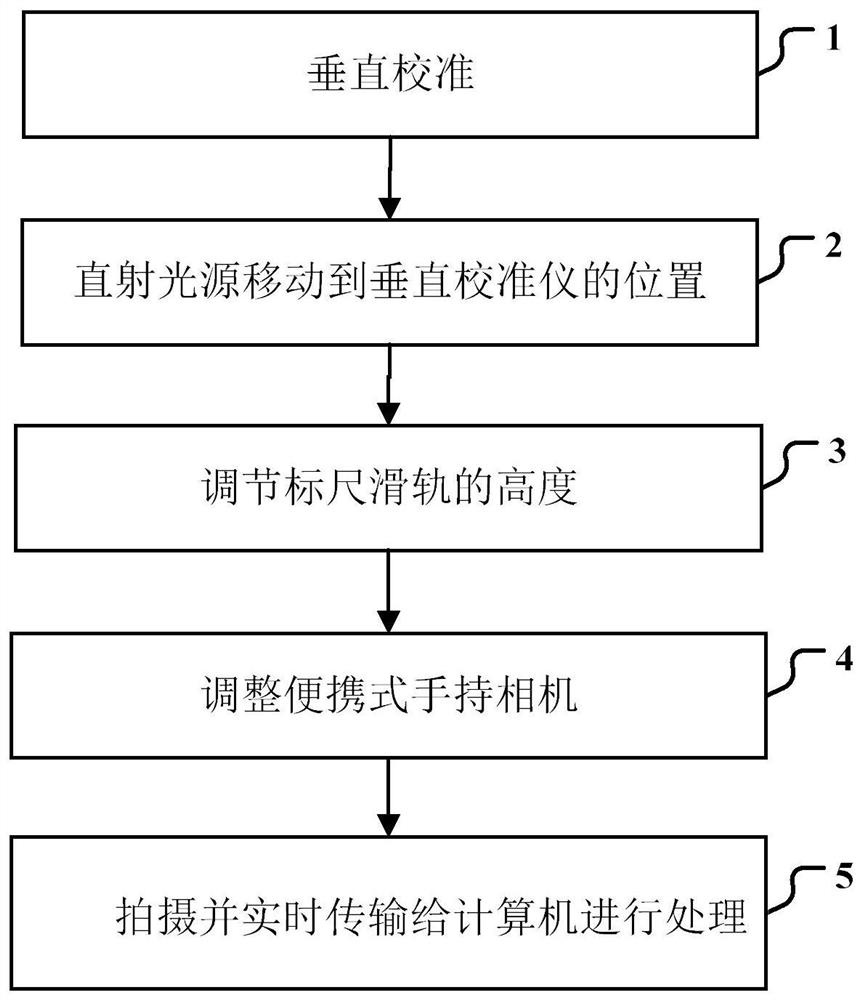
[0114] In the present embodiment, there is a scratch defect on the surface of the lens of the satellite telescope, Figure 6 There is a scratch at the upper left edge of the center, and particles formed by gas curing attach to the lens, in an irregular and scattered distribution. use Figure 1 The device shown collects an image of defects on the surface of the satellite telescope lens, opens the vertical calibrator, and illuminates the laser point in the geometric center of the measured lens placed horizontally, ensuring that the ruler slide rail is perpendicular to the measured lens. Adjust the position of the sliding assembly on the ruler slide and move the direct light source to the position of the vertical calibrator so that the center of the direct light source is on the same axis as the center of the measured lens. Adjust the height of the ruler slide so that the measured lens can be completely illuminated by the direct light source, and the portable handheld camera takes the...


PUM


Abstract

The invention discloses an LBF-based method for detecting surface defects of satellite telescope lenses. First, the clustering objective function is optimized by adding weight items and convergence items, and an iterative method is used to classify and process optical defect images. The defect contour is enhanced while the noise is removed; then, after the classified image, the LBF active contour model is used to evolve the level set function and take the zero level set to segment the defect image; finally, the extracted defect image is Quantification, using the binary chain code technology to mark the defect contour of the defect image, so as to realize the quantification of the area, center of gravity, long and short diameter and perimeter of the defect region. The present invention combines optimization of the clustering objective function for iteration, LBF active contour model for defect image segmentation and defect quantification to enhance the damage characteristics of satellite telescope lens surface defects, reveal its contour feature information, and improve the accuracy of detection accuracy. At the same time, the quantitative analysis of defects is completed.

Description

[0001] Technical neighborhood [0002] The present invention belongs to the surface defect detection technology neighborhood, more specifically, relates to a satellite telescope lens surface defect detection method based on LBF. Background [0003] Ultra-precision optics are an important part of many high-end instruments and equipment systems. In aerospace neighborhoods, a large number of optical components are used in satellites, most notably satellite telescopes, and are usually in the order of meters in diameter. For satellites, their main function is to shoot, reconnoiter and monitor the ground, so the space telescope used for satellites requires high imaging sensitivity, high precision and strong resolution. Satellite telescopes in the atmospheric environment, gas does not affect the shooting process. But in space, due to its low temperature, the gases in the nebula (such as hydrogen, methane) will solidify into particulate matter and attach to the lens, forming a surface defe...

Claims


Application Information

Patent Timeline
Patent Type & Authority Patents(China)
IPC IPC(8): G06T7/00G06T7/13G06T7/62G06T7/66G01N21/95G06V10/762G06V10/764G06K9/62
CPCG06T7/0004G06T7/13G06T7/62G06T7/66G01N21/95G06T2207/10028G06F18/23
Inventor 邱根陈薇殷春程玉华王胤泽陈凯冯怡婷
Owner UNIV OF ELECTRONICS SCI & TECH OF CHINA
Why Eureka
Try Eureka