Urban road lighting integrated system and its working method

An integrated system and road technology, applied in the direction of light guides, outdoor lighting, lighting devices, etc. of lighting systems, can solve problems such as inability to achieve stable lighting requirements, high installation costs, and reduced service life of bulbs, and achieve significant people's livelihood experience and energy saving High efficiency, low cost of production, installation and use, and convenient power adjustment

Active Publication Date: 2022-08-05
厦门鑫汇晨曦物联科技股份有限公司
View PDF0 Cites 0 Cited by
  • Summary
  • Abstract
  • Description
  • Claims
  • Application Information

AI Technical Summary

Problems solved by technology

[0003] ① Existing street lamps all use electric lamps, including sodium lamp street lamps, LED street lamps, energy-saving street lamps, new Somin xenon street lamps, etc., all of which need to consume a lot of electricity. Some solar-powered circuit lamps or wind-powered circuit lamps have low power and are affected by the external environment Large, unable to achieve stable lighting requirements;
[0004] ②Existing street lamps are easily damaged due to quality problems, internal problems or external damage, often need to replace bulbs or reconnect circuits, and require climbing vehicles to cooperate with maintenance personnel. Maintenance efficiency is low, dangers are prone to occur, and traffic is easily affected
[0005] ③Existing street lamps need to be connected with cables during installation, and the cables need to be laid in advance, which leads to high installation costs and low efficiency
[0006] ④ The suitable power of the existing street light bulbs is certain after production and installation, so it is difficult to adjust the power according to different external weather conditions, which will greatly reduce the service life of the bulbs
[0007] ⑤ Existing street lamps have many internal electrical components and high production costs

Method used


Image

  • Urban road lighting integrated system and its working method
  • Urban road lighting integrated system and its working method
  • Urban road lighting integrated system and its working method

Examples


Embodiment Construction

[0038] The present invention will be described in detail below with reference to the accompanying drawings and specific embodiments.

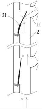
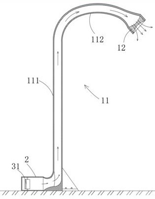
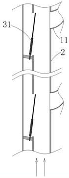
[0039] see Figures 1 to 6 , an integrated system of urban road lighting, including a street lamp system and a light guide system, the street lamp system includes a plurality of hollow cylinders 11 erected on the road at intervals and astigmatic lenses 12 respectively arranged at the upper openings of the hollow cylinders; the guide The light system includes a light guide tube 21 arranged along the street light system; the lower parts of a plurality of the hollow cylinders 11 are respectively connected with the light guide tube 21; strong light is introduced into the light guide tube 21, and the strong light is introduced into the light guide tube 21 through reflection. The hollow cylinder 11 is diffused outward through the astigmatic lens 12 to illuminate the road.

[0040]Further, in the light guide tube 21, a high-speed deflection shrapnel ...


PUM


Abstract

The invention relates to an integrated system for urban road lighting, including a street lamp system and a light guide system. The street lamp system includes a plurality of hollow cylinders erected on the road surface at intervals and astigmatism lenses respectively arranged at the upper openings of the hollow cylinders; the guide The light system includes a light guide pipe arranged along the street lamp system; the lower parts of the plurality of hollow cylinders are respectively connected with the light guide pipe; strong light is introduced into the light guide pipe, and the strong light is respectively guided into the hollow cylinder after reflection, and The astigmatism lens diffuses outward to illuminate the road surface; the urban road lighting integrated system removes the self-illumination function of street lamps and replaces it with light guiding function to achieve a unified light energy supply, so it has long service life, low energy consumption, and convenient power adjustment. , the advantages of low production, installation and use costs.

Description

technical field [0001] The invention relates to the field of urban road matching, in particular to an urban road lighting integrated system and a working method thereof. Background technique [0002] On both sides of urban roads, a matching lighting system is needed, that is, street lamps that are commonly used. Because street lamps are used more frequently, it involves road safety and people's livelihood, and there are a large number of urban roads, all of which require street lighting, which consumes a lot of energy. A long-life, low-power, high-power urban lighting system is required; the existing urban lighting systems have several obvious problems: [0003] ①Existing street lights all use electric lights, including sodium street lights, LED street lights, energy-saving street lights, new Somin xenon street lights, etc., all of which consume a lot of electricity. Some solar power generation circuit lights or wind power generation circuit lights have low power and are aff...

Claims


Application Information

Patent Timeline
Patent Type & Authority Patents(China)
IPC IPC(8): F21V13/00F21V8/00F21W131/103
CPCF21V13/00F21W2131/103
Inventor 易伟强林建勇林正飞刘书林
Owner 厦门鑫汇晨曦物联科技股份有限公司
Why Eureka
Try Eureka