Auxiliary winding device for glass fiber yarns

A winding device and glass fiber yarn technology, which is applied in glass production, transportation and packaging, thin material processing, etc., can solve the problems of reducing work efficiency, manpower consumption, physical strength, etc., and achieve the effect of reducing manual operations

Active Publication Date: 2021-06-04
元源新材料有限公司
View PDF13 Cites 2 Cited by
  • Summary
  • Abstract
  • Description
  • Claims
  • Application Information

AI Technical Summary

Problems solved by technology

[0002] Glass fiber yarn, also known as glass fiber, is an inorganic non-metallic material with excellent performance. The glass fiber yarn needs to be curled and stored after the production is completed. The existing curling method mostly uses manual measurement of the length of the glass fiber yarn, then cuts the glass fiber yarn, and finally winds it manually. This method consumes physical strength. Reduced work efficiency, so we need to design an auxiliary winding device
[0003] Patent application: CN208790914U, publication date: 20190426, discloses a glass fiber yarn winding device for non-metallic mineral products, the rotation of the operating rod, when the first elastic conductive sheet and the second elastic conductive sheet are matched by extrusion, It can achieve the effect of automatic winding of glass fiber yarn reels. The device has a simple structure and is easy to operate. The device only realizes the winding operation, and manual measurement and cutting are required, which consumes manpower.

Method used


Image

  • Auxiliary winding device for glass fiber yarns
  • Auxiliary winding device for glass fiber yarns
  • Auxiliary winding device for glass fiber yarns

Examples


Embodiment 1

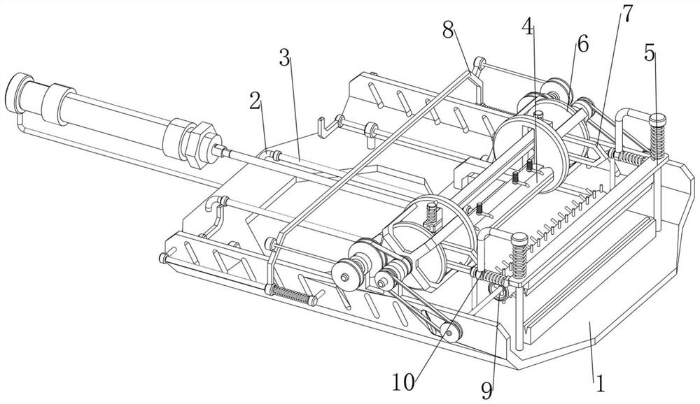
[0073] A glass fiber yarn auxiliary winding device, such as figure 1 As shown, it includes a base 1, a first support frame 2, a first slide rail 3, a clamping mechanism 4 and a cutting mechanism 5. Two first support frames 2 are symmetrically arranged on the left and right sides of the base 1, and the left and right sides are in the A first slide rail 3 is connected between two first support frames 2 on the same horizontal line, a clamping mechanism 4 is provided between the base 1 and the first slide rail 3 , and a cutting mechanism 5 is provided on the right side of the base 1 .

[0074] When people need to wind the glass fiber yarn, this glass fiber yarn auxiliary winding device can be used. First, people move the clamping mechanism 4 and the cutting mechanism 5 upwards, and then one end of the glass fiber yarn is placed on the clamping mechanism 4 Inside, people loosen the clamping mechanism 4, and the clamping mechanism 4 moves downward and resets to clamp one end of the ...

Embodiment 2

[0076] On the basis of Example 1, such as Figure 2-4 As shown, the clamping mechanism 4 includes a second support frame 41, a cylinder 42, a third support frame 43, a fourth support frame 44, a first guide rod 45, a pressing block 46 and a first spring 47, and the left part of the base 1 is provided with a There is a second support frame 41, and a cylinder 42 is installed on the second support frame 41. A third support frame 43 is slidable between the two first slide rails 3, and the expansion rod of the cylinder 42 is connected with the third support frame 43. The right side on the three bracing frames 43 is provided with a fourth bracing frame 44, and the fourth bracing frame 44 is evenly provided with four first guide rods 45, and a sliding type is provided with a pressure block 46 between the four first guide rods 45. The block 46 cooperates with the fourth support frame 44 , the first spring 47 is connected between the pressure block 46 and the first guide rod 45 , there...

Embodiment 3

[0081] On the basis of Example 2, such as Figure 5-10 As shown, it also includes a rotating mechanism 6, and the rotating mechanism 6 includes a first connecting block 61, a second connecting block 62, a second slide rail 63, a clamp 64 and a third spring 65, and the front and rear sides of the base 1 are all rotating. A first connecting block 61 is provided, and a second connecting block 62 is symmetrically arranged on the two first connecting blocks 61, and a second slide rail 63 is arranged on the outside of the second connecting block 62, and there are two upper and lower sides between the two second sliding rails 63. The clamps 64 are symmetrically arranged on the sides, and the third springs 65 are connected between the clamps 64 on the upper and lower sides and the second slide rail 63 , and the third springs 65 are wound around the second slide rail 63 .

[0082] First, people separate the two clamps 64, so that the third spring 65 is compressed, and when the pressure...


PUM


Abstract

The invention relates to a winding device, in particular to an auxiliary winding device for glass fiber yarns. The invention provides the auxiliary winding device for glass fiber yarns, which is provided with automatic cutting, rotating and clamping mechanisms. The auxiliary winding device for the glass fiber yarns comprises a base and two first supporting frames as well a first slide rail, a clamping mechanism and a cutting mechanism, wherein the two first supporting frames are symmetrically arranged at the two sides of the base; the first slide rail is connected between the two first supporting frames on the same horizontal line; the clamping mechanism is arranged between the base and the first slide rails; and the cutting mechanism is arranged on the base. A pressure block is loosened, and a first spring drives the pressure block to return for clamping ends of the glass fiber yarns, so that the clamping effect is achieved.

Description

technical field [0001] The invention relates to a winding device, in particular to a glass fiber yarn auxiliary winding device. Background technique [0002] Glass fiber yarn, also known as glass fiber, is an inorganic non-metallic material with excellent performance. The glass fiber yarn needs to be curled and stored after the production is completed. The existing curling method mostly uses manual measurement of the length of the glass fiber yarn, then cuts the glass fiber yarn, and finally winds it manually. This method consumes physical strength. Reduced work efficiency, so we need to design an auxiliary winding device. [0003] Patent application: CN208790914U, publication date: 20190426, discloses a glass fiber yarn winding device for non-metallic mineral products, the rotation of the operating rod, when the first elastic conductive sheet and the second elastic conductive sheet are matched by extrusion, It can achieve the effect of automatic winding of the glass fiber...

Claims


Application Information

Patent Timeline
IPC IPC(8): B65H75/28B65H54/70B65H71/00D06H7/02
CPCB65H75/28B65H54/702B65H71/00D06H7/02B65H2701/1742Y02P40/57
Inventor 张全文张廷然张鸿乐陈伟萍周扬
Owner 元源新材料有限公司
Why Eureka
Try Eureka