Metal plate bending device

A bending device and sheet metal technology, applied in the field of sheet metal bending devices, can solve the problems of large cost investment

Inactive Publication Date: 2021-06-04
ZHANGJIAJIE INST OF AERONAUTICAL ENG
View PDF0 Cites 0 Cited by
  • Summary
  • Abstract
  • Description
  • Claims
  • Application Information

AI Technical Summary

Problems solved by technology

[0002] As we all know, bending tools are commonly used tool equipment in the processing of sheet metal products. With the rapid upgrading of products and the arrival of the era of multi-variety and small batch production, the frequency of tool replacement is high. For the production cycle of tools, the standardization requirements are becoming more and more At the same time, it is very important to reduce the weight of the tool and reduce the labor intensity of the mold change. The existing bending tool mainly places the workpiece on the lower tool, and stamps the workpiece through the stamping head of the upper tool to complete the bending of the workpiece. The bending angle of the workpiece is mainly determined by the groove of the lower tool, and the bending degree of the bending part of the different workpiece is different in the groove. In the actual production process, because the length of the groove is fixed, each A lower cutting tool can only meet the requirements of one bending process. However, the bending process requirements in actual production are varied, so that the manufacturer must configure a large number of supporting tools, and the cost investment is large.

Method used


Image

  • Metal plate bending device
  • Metal plate bending device
  • Metal plate bending device

Examples


Embodiment Construction

[0018] The specific implementation manners of the present invention will be further described in detail below in conjunction with the accompanying drawings and embodiments. The following examples are used to illustrate the present invention, but are not intended to limit the scope of the present invention.

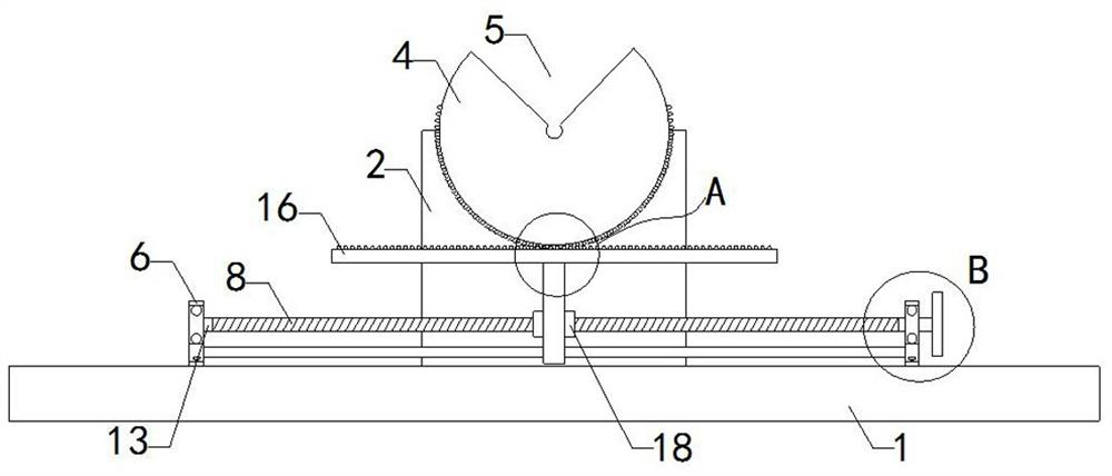
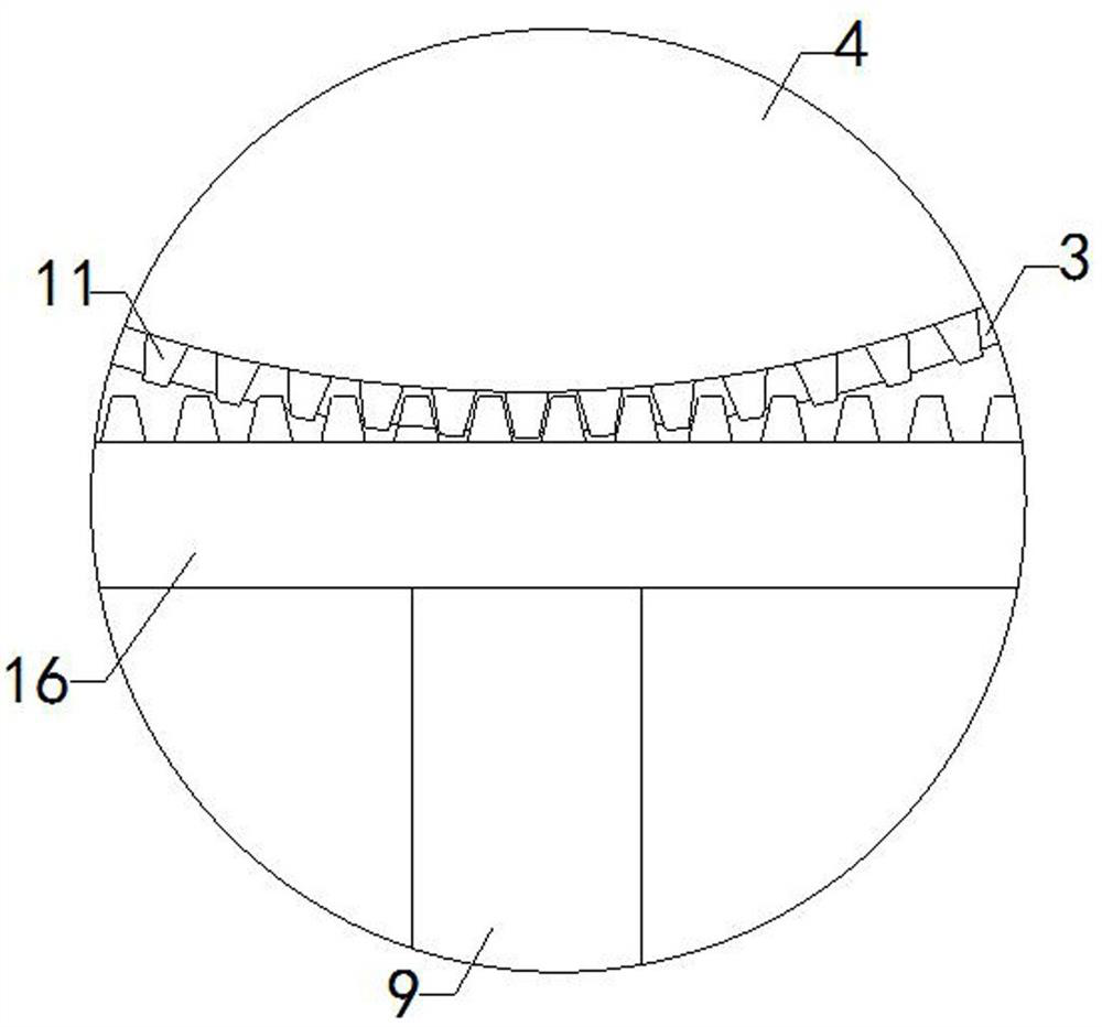
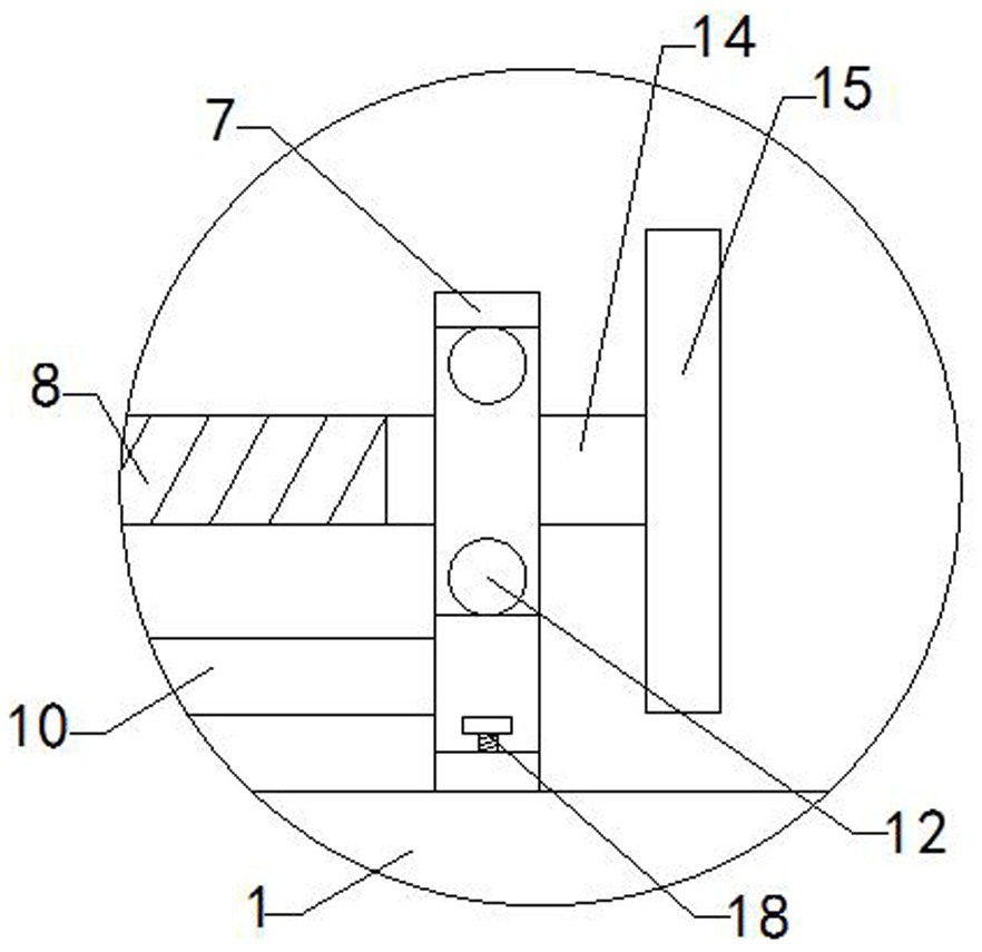
[0019] like Figure 1 to Figure 5 As shown, a sheet metal bending device of the present invention includes a base 1, a support block 2 is provided on the top of the base 1, and a mounting groove connected to the front and rear is provided on the top of the support block 2, and multiple sets of protrusions are provided on the inner wall of the mounting groove 3. The cross-section shape of each group of protrusions 3 is isosceles trapezoidal, and also includes a cylinder 4. The top of the cylinder 4 is provided with a V-shaped groove 5 connected to the front and back, and the bottom of the V-shaped groove 5 coincides with the axis of the cylinder 4. , the outer wall of cyli...


PUM


Abstract

The invention relates to the technical field of bending accessory devices, and in particular relates to a metal plate bending device. The metal plate bending device is simple in structure, adjustable in metal plate bending angle and capable of reducing manufacturing cost. The metal plate bending device comprises a base; a supporting block is arranged at the top of the base; a mounting groove which is communicated in the front-back direction is formed in the top of the supporting block; multiple sets of protrusions are arranged on the inner side wall of the mounting groove; the section of each set of protrusions is in an isosceles trapezoid shape; the metal plate bending device further comprises a cylinder; a V-shaped groove which is communicated in the front-back direction is formed in the top of the cylinder; the bottom of the V-shaped groove coincides with the axis of the cylinder; multiple sets of grooves in sliding fit with the multiple sets of protrusions are formed in the outer side wall of the cylinder; the metal plate bending device further comprises a front moving mechanism and a rear moving mechanism; the front moving mechanism comprises a front supporting rod, a front stabilizing rod, a front threaded rod, a front moving block and a front transverse rod; and the rear moving mechanism comprises a rear supporting rod, a rear stabilizing rod, a rear threaded rod, a rear moving block and a rear transverse rod.

Description

technical field [0001] The invention relates to the technical field of bending attachments, in particular to a sheet metal bending device. Background technique [0002] As we all know, bending tools are commonly used tool equipment in the processing of sheet metal products. With the rapid upgrading of products and the arrival of the era of multi-variety and small batch production, the frequency of tool replacement is high. For the production cycle of tools, the standardization requirements are becoming more and more At the same time, it is very important to reduce the weight of the tool and reduce the labor intensity of the mold change. The existing bending tool mainly places the workpiece on the lower tool, and stamps the workpiece through the stamping head of the upper tool to complete the bending of the workpiece. The bending angle of the workpiece is mainly determined by the groove of the lower tool, and the bending degree of the bending part of the different workpiece i...

Claims


Application Information

Patent Timeline
Patent Type & Authority Applications(China)
IPC IPC(8): B21D5/01
CPCB21D5/01
Inventor 彭武运邵伟芹朱阁陈立侯德政
Owner ZHANGJIAJIE INST OF AERONAUTICAL ENG
Why Eureka
Try Eureka