Industrial spraying robot
A spraying robot and industrial technology, applied in the direction of manipulators, manufacturing tools, spraying devices, etc., can solve the problems of high labor intensity, low spraying efficiency, cumbersome operation, etc.
- Summary
- Abstract
- Description
- Claims
- Application Information
AI Technical Summary
Problems solved by technology
Method used
Image
Examples
Embodiment 1
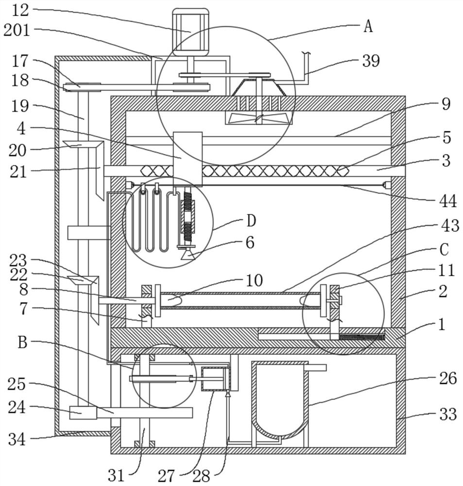
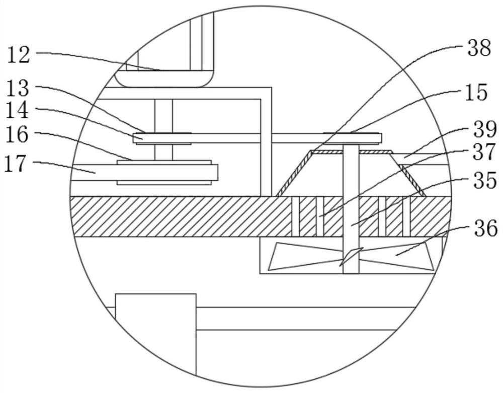
[0031] refer to figure 1 , Figure 4 , Figure 5 , an industrial spraying robot, comprising a workbench 1 and a part to be sprayed 43, a support frame 2 is fixedly connected to the workbench 1, a driving mechanism is fixedly connected to the support frame 2, a screw rod 3 is connected to the support frame 2 in rotation, and the screw rod 3 is provided with a reciprocating chute 5, the reciprocating chute 5 is slidably connected with a slider 4, the slider 4 is fixedly connected with a nozzle 6, the workbench 1 is fixedly connected with a first fixing seat 7, and the workbench 1 is fixedly connected with There is a second fixed seat 11, the first fixed seat 7 and the second fixed seat 11 are rotatably connected with a fixed block 10, the painted part 43 is sleeved on the fixed block 10, and the driving mechanism rotates with the screw mandrel 3 and the fixed block 10 connected.
[0032] The driving mechanism comprises a motor 12, a first driving wheel 13, a first transmissio...
Embodiment 2
[0043] refer to image 3 , an industrial spraying robot, comprising a workbench 1 and a part to be sprayed 43, a support frame 2 is fixedly connected to the workbench 1, a driving mechanism is fixedly connected to the support frame 2, a screw rod 3 is connected to the support frame 2 in rotation, and the screw rod 3 is provided with a reciprocating chute 5, the reciprocating chute 5 is slidably connected with a slider 4, the slider 4 is fixedly connected with a nozzle 6, the workbench 1 is fixedly connected with a first fixing seat 7, and the workbench 1 is fixedly connected with There is a second fixed seat 11, the first fixed seat 7 and the second fixed seat 11 are rotatably connected with a fixed block 10, the painted part 43 is sleeved on the fixed block 10, and the driving mechanism rotates with the screw mandrel 3 and the fixed block 10 connected.
[0044] The driving mechanism comprises a motor 12, a first driving wheel 13, a first transmission belt 14, a first driven ...
Embodiment 3
[0055] refer to figure 1 , figure 2 , Figure 6 , an industrial spraying robot, comprising a workbench 1 and a part to be sprayed 43, a support frame 2 is fixedly connected to the workbench 1, a driving mechanism is fixedly connected to the support frame 2, a screw rod 3 is connected to the support frame 2 in rotation, and the screw rod 3 is provided with a reciprocating chute 5, the reciprocating chute 5 is slidably connected with a slider 4, the slider 4 is fixedly connected with a nozzle 6, the workbench 1 is fixedly connected with a first fixing seat 7, and the workbench 1 is fixedly connected with There is a second fixed seat 11, the first fixed seat 7 and the second fixed seat 11 are rotatably connected with a fixed block 10, the painted part 43 is sleeved on the fixed block 10, and the driving mechanism rotates with the screw mandrel 3 and the fixed block 10 connected.
[0056] The driving mechanism comprises a motor 12, a first driving wheel 13, a first transmissio...
PUM
 Abstract
Description
Claims
Application Information
 - R&D
- Intellectual Property
- Life Sciences
- Materials
- Tech Scout
- Unparalleled Data Quality
- Higher Quality Content
- 60% Fewer Hallucinations
Browse by: Latest US Patents, China's latest patents, Technical Efficacy Thesaurus, Application Domain, Technology Topic, Popular Technical Reports.
© 2025 PatSnap. All rights reserved.Legal|Privacy policy|Modern Slavery Act Transparency Statement|Sitemap|About US| Contact US: help@patsnap.com


