Multi-machine-head water chilling unit

A chiller and multi-head technology, which is applied to refrigeration components, compressors with multiple evaporators, refrigerators, etc., can solve the problem of unsatisfactory working effect of the overall chiller, uneven heat transfer of heat exchangers, etc. question

Pending Publication Date: 2021-06-01
QINGDAO HAIER AIR CONDITIONING ELECTRONICS CO LTD +1
View PDF0 Cites 0 Cited by
  • Summary
  • Abstract
  • Description
  • Claims
  • Application Information

AI Technical Summary

Problems solved by technology

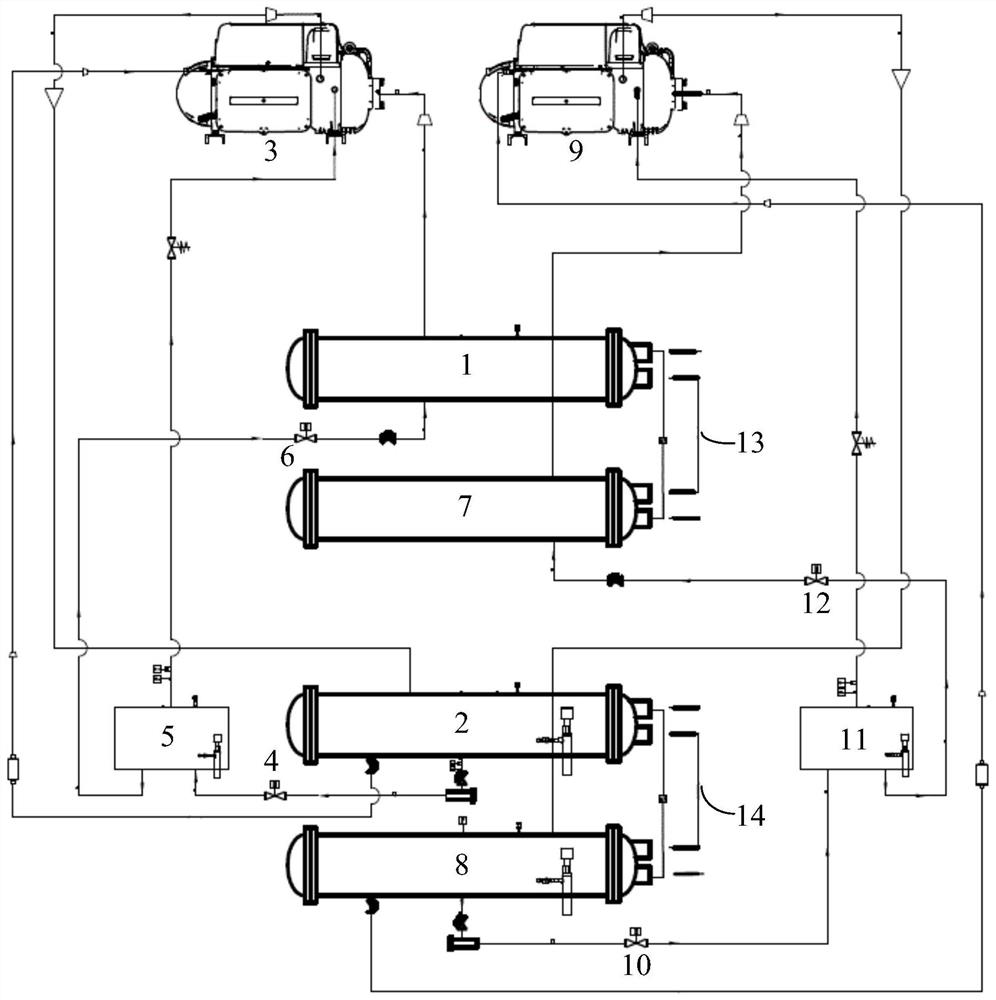
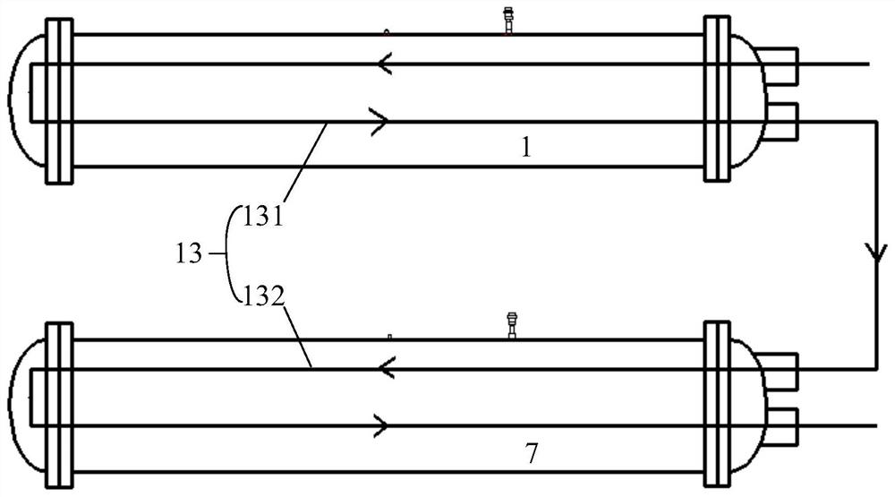
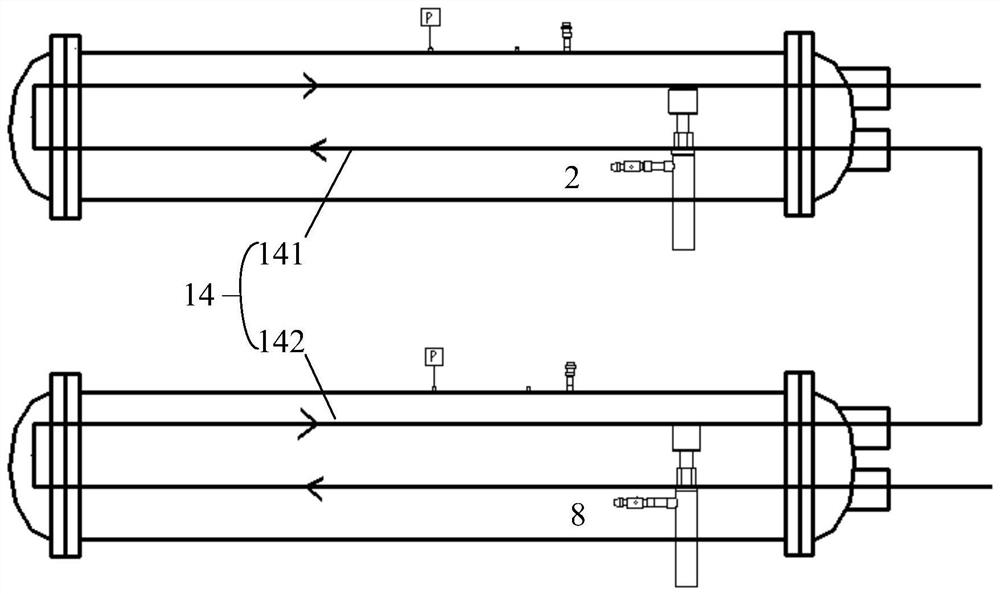
[0005] In order to solve the above-mentioned problems in the prior art, that is, in order to solve the problem that the heat exchange heat of the heat exchanger is not uniform when the two units of the existing in-line multi-head chiller are running, and the working effect of the overall chiller is not ideal, The present invention provides a multi-head chiller, which includes a first evaporator, a first condenser, a first compressor, a first throttling device, a second evaporator, and a second condenser , the second compressor and the second throttling device, wherein, the first evaporator, the first condenser, the first compressor and the first throttling device are communicated into one through a refrigerant delivery pipeline A closed loop, the second evaporator, the second condenser, the second compressor, and the second throttling device are connected to form another closed loop through the refrigerant delivery pipeline, and the multi-head chiller further comprising a first heat exchange system capable of exchanging heat with the first evaporator and the second evaporator and a second heat exchange system capable of exchanging heat with the first condenser and the second condenser, Both the first heat exchange system and the second heat exchange system include two water delivery pipelines, and one of the two water delivery pipelines can be connected to the first evaporator or the first condenser heat exchange, the other of the two water delivery pipelines can exchange heat with the second evaporator or the second condenser, the first heat exchange system and the second heat exchange system At least one of the configurations is: the two water delivery pipelines can exchange heat independently with the first evaporator or the first condenser and the second evaporator or the second condenser respectively string together

Method used


Image

  • Multi-machine-head water chilling unit
  • Multi-machine-head water chilling unit
  • Multi-machine-head water chilling unit

Examples


Embodiment Construction

[0026] It should be understood by those skilled in the art that, in the description of the present invention, terms such as "front", "rear", "horizontal" and other indicated directions or positional relationships are based on the directions or positional relationships shown in the accompanying drawings, which It is for the convenience of description only, and does not indicate or imply that the device or element must have a specific orientation, be constructed and operate in a specific orientation, and thus should not be construed as limiting the present invention. In addition, the terms "first", "second", "third", and "fourth" are used for descriptive purposes only, and should not be construed as indicating or implying relative importance.

[0027] In addition, it should be noted that, in the description of the present invention, unless otherwise clearly stipulated and limited, the terms "installation", "connection" and "connection" should be understood in a broad sense, for e...


PUM


Abstract

The invention belongs to the technical field of heat exchange equipment, and particularly relates to a multi-machine-head water chilling unit. The invention aims to solve the problems that when two units of an existing in-line multi-machine-head water chilling unit operate, the heat exchange amount of a heat exchanger is not uniform, and the working effect of the whole water chilling unit is not ideal. In order to achieve the purpose, two water conveying pipelines included in at least one of two heat exchange systems of the multi-machine-head water chilling unit are arranged to be capable of independently exchanging heat with evaporators or condensers of two units while being connected in series. By means of the arrangement, the problem that the heat exchange amount of at least one set of heat exchangers (namely the two evaporators or the two condensers) of the multi-machine-head water chilling unit is not uniform can be solved to a great extent, the refrigerating capacity of the multi-machine-head water chilling unit is improved, and the energy efficiency ratio parameter of the multi-machine-head water chilling unit is optimized.

Description

technical field [0001] The invention belongs to the technical field of heat exchange equipment, and in particular relates to a multi-head chiller. Background technique [0002] The multi-head chiller includes multiple completely independent units with refrigerant circulation circuits, such as two. Most of the existing multi-head chillers are in-line. When the two units are running, the water heat exchange pipes of the evaporators and condensers of the two units are connected in series in a mixed manner, that is, the evaporation of one unit After the water entering the evaporator starts heat exchange, during the heat exchange of the evaporator, the water will flow through the evaporation of another unit for heat exchange, and then flow back to this evaporator to continue the heat exchange, thus completing the heat exchange of the two evaporators Work, the heat exchange process of the condensers of the two units is the same as the above process. [0003] In this case, becaus...

Claims


Application Information

Patent Timeline
Patent Type & Authority Applications(China)
IPC IPC(8): F25B5/02F25B41/20F25B49/02
CPCF25B5/02F25B49/02F25B41/20F24F3/00F25B30/06
Inventor 邓善营张捷郑修新孟庆超
Owner QINGDAO HAIER AIR CONDITIONING ELECTRONICS CO LTD
Why Eureka
Try Eureka