
A fastening structure and method for a prefabricated building formwork

A technology for building templates and fastening structures, which is applied in building construction, on-site preparation of building components, construction, etc. It can solve problems such as difficulty in ensuring verticality of walls, troublesome end handling, cumbersome operations, etc., and achieves installation and reinforcement Convenient and fast, high reuse rate, high quality assurance effect

Active Publication Date: 2022-05-24
JIANGSU SUZHONG CONSTR GROUP
View PDF0 Cites 0 Cited by
  • Summary
  • Abstract
  • Description
  • Claims
  • Application Information

AI Technical Summary

Problems solved by technology

This method adds an additional casing process, which needs to be prepared according to the width of the wall, which is cumbersome to operate. Leaving the casing in the wall not only increases the cost, but also troublesome end processing in the later stage, which wastes manpower.
[0003] Moreover, as the thickness of the wall changes, the size of the fasteners also needs to be changed accordingly. In the prior art, changing the tightness of the screw can change the size, but the adjustment is time-consuming and laborious. It is necessary to measure and adjust each screw, and the process is time-consuming. It is laborious, and the adjustment amount on both sides is also difficult to keep consistent, which makes it difficult to guarantee the verticality of the wall

Method used


Image

  • A fastening structure and method for a prefabricated building formwork
  • A fastening structure and method for a prefabricated building formwork
  • A fastening structure and method for a prefabricated building formwork

Examples


Embodiment 1

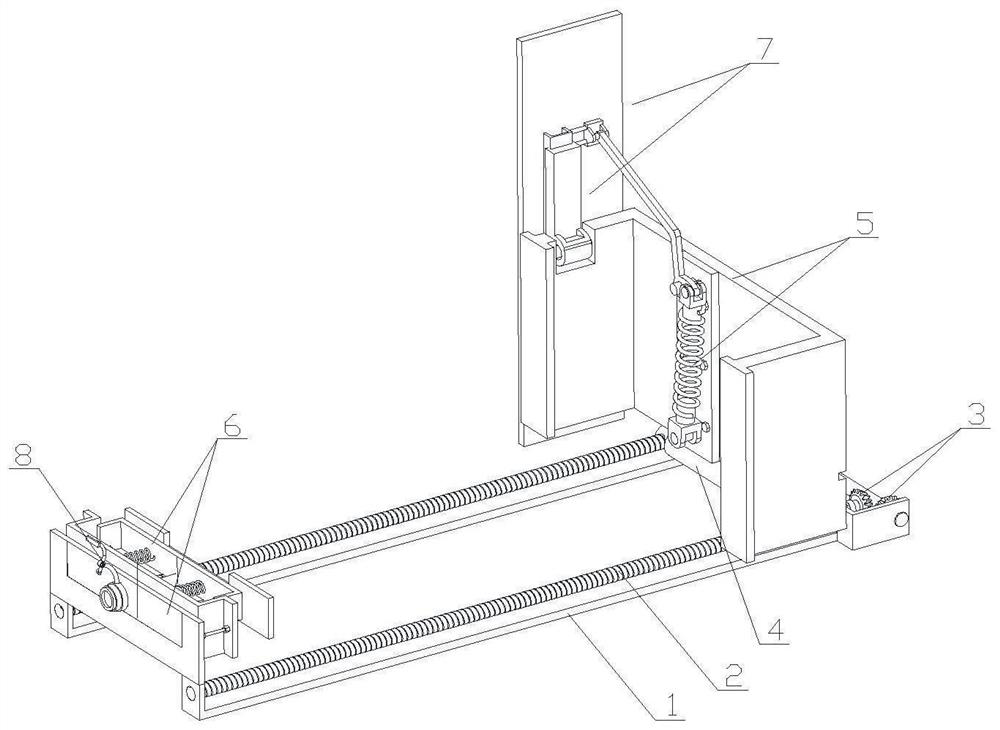
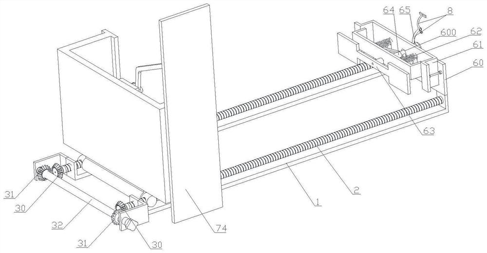
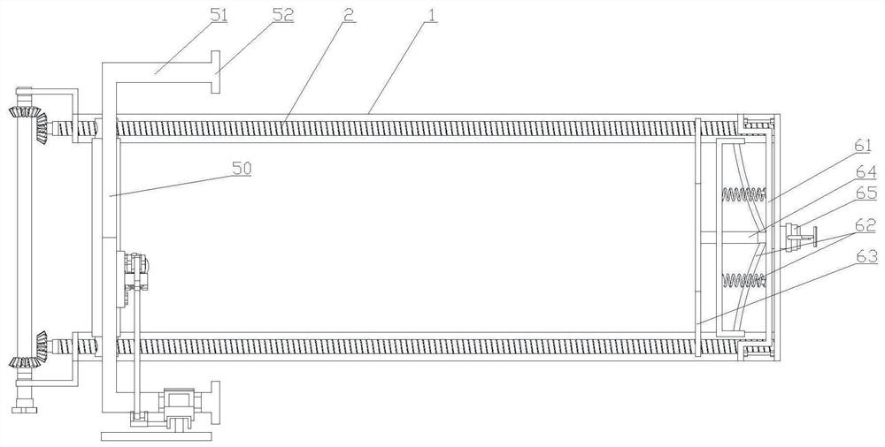
[0046] see Figure 1 to Figure 8 The technical solution provided by the present invention is that a prefabricated building formwork fastening structure comprises two guide seats 1 arranged oppositely, two drive screws 2 respectively arranged on the two guide seats 1, and one end of the two drive screws 2 is provided with a drive The rotating gear drive assembly 3 is provided with a reciprocating moving assembly 4 that reciprocates along the two driving screws 2 between the two driving screws 2. There is also an elastic clamping assembly 6 opposite to the moving clamping member 5 therebetween.

[0047] Specifically, the movable clamping member 5 includes a carrier plate 50, and two lateral limit plates 51 are respectively provided on both sides of the carrier plate 50. Each side limit plate 51 is provided with a lateral clip plate 52, which is mounted on the carrier plate 50. The inner side of the plate 50 is provided with an elastic return mechanism 53 , and between the elast...

Embodiment 2

[0067] On the basis of Embodiment 1, the elastic clamping component 6 can also be other elastic clamping components that move along the axis of the drive screw 2, so as to realize the reinforcement and fine adjustment of the positioning of the formwork on both sides of the wall.


PUM


Abstract

The present invention provides a fastening structure of an assembled building formwork and a method thereof. The fastening structure of the assembled building formwork includes two oppositely arranged guide seats, two transmission screws, a gear drive assembly, a reciprocating movement assembly, and a reciprocating movement assembly A movable clamping part is provided on the top, and an elastic clamping assembly opposite to the movable clamping part is arranged between the two transmission screws; the method includes the following steps: S1, placing the fastening device; S2, adjusting the movable clamping part The distance from the elastic clamping component; S3, rotate the limit splint of the mobile clamping part 90 degrees until the assembled formwork on both sides of the wall is clamped and fixed; S4, finely adjust the distance between the backing plate component and the building formwork distance between. The beneficial effects of the present invention are: the present invention can continuously adjust the corresponding dimensional changes according to the needs along with the change of the thickness of the wall, so as to realize the clamping of the building formwork on both sides of the wall.

Description

technical field [0001] The invention relates to the technical field of prefabricated building formwork fixing, in particular to a prefabricated building formwork fastening structure and a method thereof. Background technique [0002] During the construction of prefabricated building formwork, tightening rods are often used to fix the formwork on both sides. Generally, the traditional method is to use a screw. The fastening length needs to be consistent to ensure the verticality of the wall. During assembly, the number of screws is huge, and each needs to be adjusted manually, and the length must be consistent, which shows that the amount of engineering is huge. After the building formwork is assembled, it is very laborious to pull out the pull screw, and it cannot be used in turnaround. The current method is to install a casing on the outside of the screw, the casing is located in the wall, and the assembled casing is left in the wall, but the screw is pulled out. This met...

Claims


Application Information

Patent Timeline
Patent Type & Authority Patents(China)
IPC IPC(8): E04G17/065
CPCE04G17/065E04G17/0655
Inventor 于海峰涂淼栋丁杰严进
Owner JIANGSU SUZHONG CONSTR GROUP
Learn More