Rapid dredging device

A dredging device and fast technology, applied in the direction of earth mover/shovel, mechanically driven excavator/dredger, construction, etc., which can solve the problem of reduced water treatment capacity, low efficiency of sewage suction pump, and incompatibility with mine continuity. production and other issues to achieve the effect of increasing capacity

Pending Publication Date: 2021-06-01
FUJIAN MAKENG MINING CO LTD
View PDF5 Cites 1 Cited by
  • Summary
  • Abstract
  • Description
  • Claims
  • Application Information

AI Technical Summary

Problems solved by technology

[0002] When the mine is excavated, the underground roadway ditch needs to be dredged frequently, and the silt is deposited at the bottom of the ditch, and the efficiency of the sewage suction pump is low and the work is slow; in addition, the groundwater must be continuously pumped up to the ground until the sedimentation tank, the water in the sedimentation tank It needs to be discharged after treatment and work continuously; however, the sludge at the bottom of the sedimentation tank occupies a large volume of the sedimentation tank, which reduces the amount of water treatment per unit time and affects the progress of continuous work, so it is necessary to quickly clean up the sludge; currently, sewage suction is used The pump is used for cleaning. In order to reduce the deposition of silt at the bottom, a stirring device will be used for stirring in advance. However, after stirring, most of the silt still sinks to the bottom, and part of it forms muddy water. The sewage suction efficiency is still relatively low, which does not meet the requirements of continuous production in mines.

Method used


Image

  • Rapid dredging device

Examples


Embodiment Construction

[0016] In order to make the object and technical solutions of the present invention clearer, the present invention will be further described below in conjunction with the accompanying drawings and embodiments:

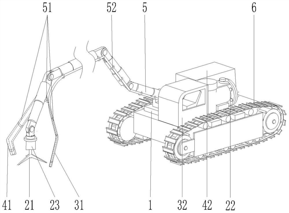
[0017] Such as figure 1 A kind of rapid dredging device shown, comprises: base 1, is provided with stirring device, air injection device, sewage suction device; Said stirring device is connected with stirring blade 21; Said air injection device is connected with high-pressure pipeline 31; The sewage suction device is connected with a sewage suction pipeline 41; the mechanical arm 5 is installed and fixed on the base 1; the front end of the mechanical arm 5 is fixedly connected to the stirring blade 21, the high-pressure pipeline 31 and the sewage suction pipeline 41 ; The control device (not shown in the figure) controls the work of the mechanical arm 5, the stirring device, the air injection device and the sewage suction device.

[0018] Preferably, a mounting frame ...


PUM


Abstract

The invention provides a rapid dredging device which comprises a base, a mechanical arm and a control device. A stirring device, an air spraying device and a sewage suction device are arranged on the base. The stirring device is connected with stirring blades; the air spraying device is connected with a high-pressure pipeline; and the sewage suction device is connected with a sewage suction pipeline. The mechanical arm is mounted on and fixed to the base, and the front end of the mechanical arm is fixedly connected with the stirring blades, the high-pressure pipeline and the sewage suction pipeline. The control device is used for controlling the mechanical arm, the stirring device, the air spraying device and the sewage suction device to work. According to the rapid dredging device provided by the invention, the position is flexibly adjusted through the mechanical arm, sludge is scattered through the stirring device first, then the sludge is blown up through the air spraying device to float in water, most of the sludge turns into muddy water, meanwhile, the muddy water is sucked away through a sludge suction pump, the sludge can be rapidly cleaned up, the capacity of a water pool is increased, and preparation is made for the next step of water pumping within the shortest time, and the demand for continuous production of mines is met.

Description

technical field [0001] The invention relates to a quick dredging device. Background technique [0002] When the mine is excavated, the underground roadway ditch needs to be dredged frequently, and the silt is deposited at the bottom of the ditch, and the efficiency of the sewage suction pump is low and the work is slow; in addition, the groundwater must be continuously pumped up to the ground until the sedimentation tank, the water in the sedimentation tank It needs to be discharged after treatment and work continuously; however, the sludge at the bottom of the sedimentation tank occupies a large volume of the sedimentation tank, which reduces the amount of water treatment per unit time and affects the progress of continuous work, so it is necessary to quickly clean up the sludge; currently, sewage suction is used The pump is used to clean the sewage. In order to reduce the deposition of sludge at the bottom, a stirring device is used to stir in advance. However, after stirr...

Claims


Application Information

Patent Timeline
IPC IPC(8): E02F5/28E02F3/88E02F3/90E02F3/92
CPCE02F5/28E02F3/8816E02F3/90E02F3/92
Inventor 吴梅发董军庭林阳辉王选魏烜昌
Owner FUJIAN MAKENG MINING CO LTD
Why Eureka
Try Eureka