Industrial batten fixed-distance cutting machine
A cutting machine and industrial technology, which is applied in the field of industrial wooden strip fixed-distance cutting machines, can solve the problems of low working efficiency of wooden strips and difficulty in ensuring cutting, and achieve the effect of facilitating work and improving work efficiency
- Summary
- Abstract
- Description
- Claims
- Application Information
AI Technical Summary
Problems solved by technology
Method used
Image
Examples
Embodiment 1
[0086] An industrial wood strip cutting machine, such as figure 1 As shown, it includes a base plate 1, a feeding mechanism 2, a distance-fixing mechanism 3 and a cutting mechanism 4. The feeding mechanism 2 is provided on the left side of the top front side of the base plate 1, and the distance-fixing mechanism 3 is provided on the left side of the top front side of the base plate 1. The base plate 1 A cutting mechanism 4 is arranged between the left part of the top front side and the feeding mechanism 2 .
[0087] When people need to cut the wooden strips, first adjust the length of the wooden strips that need to be cut out by the fixed distance mechanism 3, then put the wooden strips on the right side of the feeding mechanism 2, and then start a certain part of the feeding mechanism 2, and feed Mechanism 2 transmits the wooden strips to the left, and the feeding mechanism 2 drives the cutting mechanism 4 to run. With the cooperation of the distance mechanism 3, the cutting ...
Embodiment 2
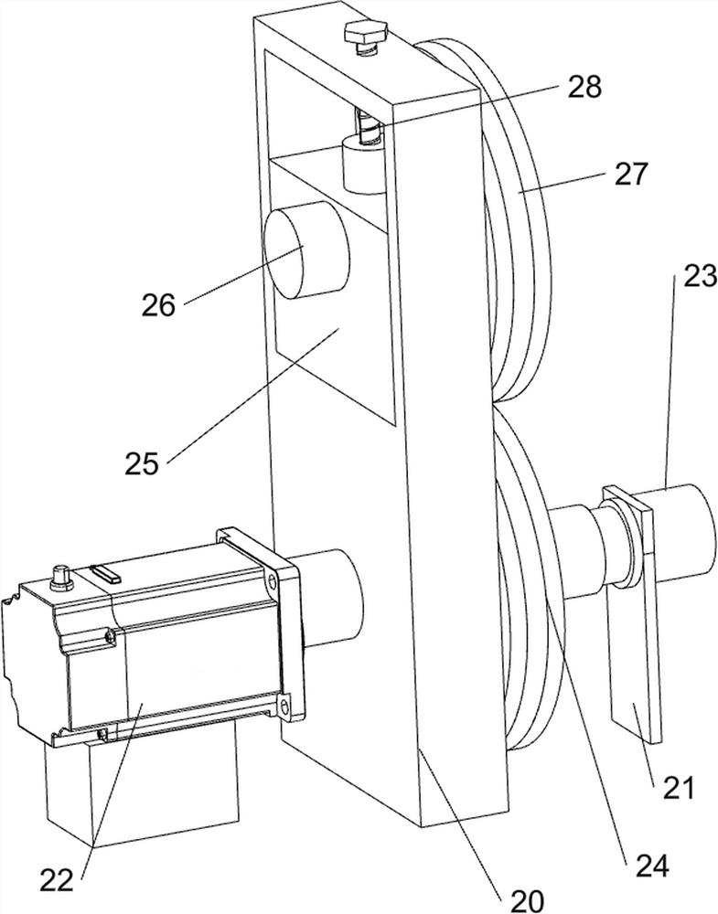
[0089] On the basis of Example 1, such as figure 2 , image 3 , Figure 4 with Figure 5 As shown, the feeding mechanism 2 includes a support seat 20, a first support plate 21, a first motor 22, a first transmission shaft 23, a first wheel disc 24, a first sliding block 25, a second transmission shaft 26, a second wheel Disk 27 and screw rod 28, base plate 1 top front left side is provided with support base 20, base plate 1 top front left side is provided with first support plate 21, first support plate 21 is positioned at support base 20 front side, base plate 1 top left The middle part of the side is provided with a first motor 22, the output shaft of the first motor 22 is provided with a first transmission shaft 23, the first transmission shaft 23 is rotationally connected with the support seat 20 and the first support plate 21, and the middle part of the first transmission shaft 23 is provided with There is a first wheel 24, the upper part of the support seat 20 is sli...
Embodiment 3
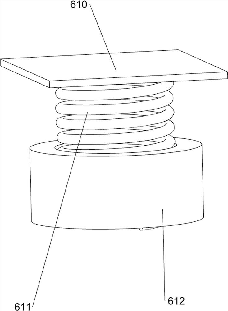
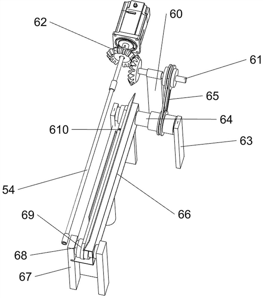
[0095] On the basis of Example 2, such as Image 6 , Figure 7 , Figure 8 with Figure 9 As shown, it also includes a material distribution mechanism 5, and the material distribution mechanism 5 includes a fourth support plate 50, a blanking plate 51, a material stopper 52, a second motor 53, a fourth transmission shaft 54 and a material distribution cylinder 55, and the bottom plate 1 The right part of the rear side of the top is left and right symmetrical to the fourth support plate 50, and the upper part of the fourth support plate 50 is provided with a blanking plate 51. A second motor 53 is provided, and a fourth transmission shaft 54 is rotatably arranged between the front side of the upper part of the fourth support plate 50. The right end of the fourth transmission shaft 54 is connected with the output shaft of the second motor 53, and the fourth transmission shaft 54 is provided with Distribution drum 55.
[0096] Also includes a transport mechanism 6, th...
PUM
 Abstract
Description
Claims
Application Information
 - R&D
- Intellectual Property
- Life Sciences
- Materials
- Tech Scout
- Unparalleled Data Quality
- Higher Quality Content
- 60% Fewer Hallucinations
Browse by: Latest US Patents, China's latest patents, Technical Efficacy Thesaurus, Application Domain, Technology Topic, Popular Technical Reports.
© 2025 PatSnap. All rights reserved.Legal|Privacy policy|Modern Slavery Act Transparency Statement|Sitemap|About US| Contact US: help@patsnap.com


