Turning clamp for blind flange

A flange blind plate and turning technology, which is applied in the direction of turning equipment, turning equipment, manufacturing tools, etc., can solve the problems that affect the feeding of turning tools, and the three-jaw chuck cannot meet the needs of clamping flange blind plate blanks, etc. , to achieve the effect of improving turning accuracy, reducing clamping error and improving machining accuracy

Active Publication Date: 2021-06-01
济南江华锻铸机械有限公司
View PDF11 Cites 3 Cited by
  • Summary
  • Abstract
  • Description
  • Claims
  • Application Information

AI Technical Summary

Problems solved by technology

[0005] In view of the above-mentioned related technologies, the inventor believes that since there is no hole in the middle of the flange blind plate, the blank of the flange blind plate is mostly a circular plate, and when clamping the blank, the three-jaw chuck can only hold the blank When turning the outer peripheral surface of the blank, the jaws of the three-jaw chuck will affect the feed of the turning tool, so the ordinary three-jaw chuck cannot meet the needs of clamping the flange blank blank

Method used


Image

  • Turning clamp for blind flange
  • Turning clamp for blind flange
  • Turning clamp for blind flange

Examples


Embodiment Construction

[0039] The following is attached Figure 1-6 The application is described in further detail.

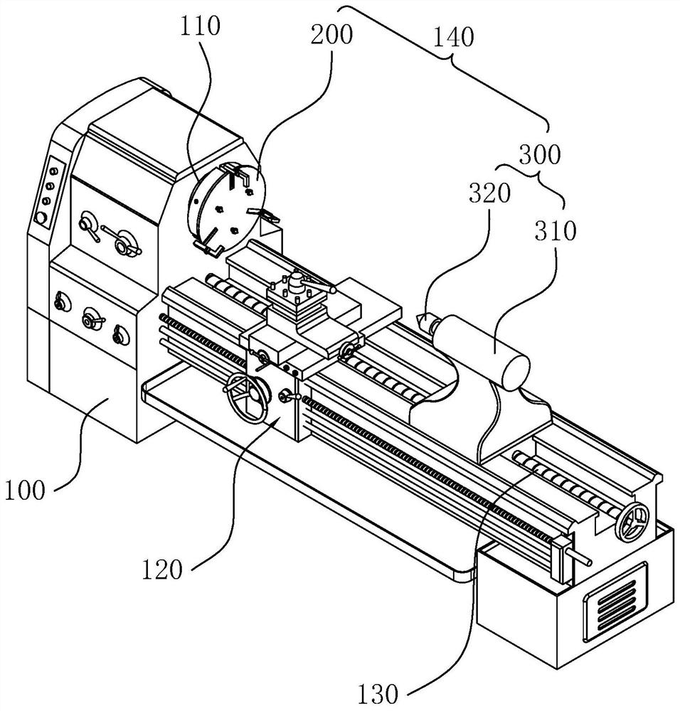
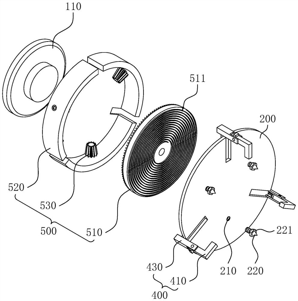
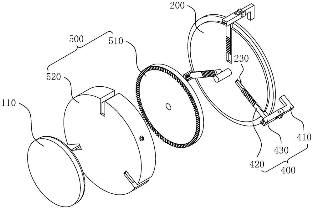
[0040] The embodiment of the present application discloses a turning fixture for a flange blind plate. refer to figure 1 and figure 2 , the turning jig 140 of the flange blind plate includes a base plate 200 as a basic support, a first pressing mechanism 300 and a second pressing mechanism 400 for pressing the blank. The base plate 200 is set on the spindle 110 of the lathe, the first edge mechanism is set on the frame 100 of the lathe, and the second pressing mechanism 400 is set on the base plate 200 .

[0041] refer to figure 1 and figure 2 , the base plate 200 has a circular cross-section, and the base plate 200 is coaxially fixedly connected to the spindle 110 of the lathe through a coupling. Most of the main shaft 110 of the lathe is coaxially fixed with a three-jaw chuck through a coupling. In other embodiments, the three-jaw chuck can also be used to clamp the subst...


PUM


Abstract

The invention relates to a turning clamp for a blind flange, and relates to the technical field of metal machining equipment. The turning clamp for the blind flange comprises a base plate, a first pressing mechanism and a second pressing mechanism, wherein the first pressing mechanism comprises a tailstock and a tail cone; the tail cone is rotatably connected onto the tailstock; the tail cone and the base plate are coaxially arranged; the base plate is coaxially and fixedly connected onto a main shaft of a lathe; the second pressing mechanism comprises a clamping jaw; and the clamping jaw is connected onto the base plate in a sliding mode. According to the turning clamp for the blind flange provided by the invention, when the peripheral face of a workblank is machined, the base plate and the tail cone are used for clamping the workblank, so that the peripheral face of the workblank can be completely exposed outside; and when a boss of theworkblank is machined, the workblank is clamped by the base plate and the clamping jaw, so that the axis part of the workblank can be completely exposed outside, and feeding of a turning tool is facilitated.

Description

technical field [0001] The present application relates to the field of metal processing equipment, in particular to a turning fixture for a flange blind plate. Background technique [0002] Blind flange, also known as blind flange, is a form of flange and can be understood as a flange without a hole in the middle. The function of the flange blind plate: one is to block the end of the pipeline, and the other is to facilitate the removal of debris in the pipeline during maintenance. As far as the plugging effect is concerned, it has the same function as the head and the pipe cap, but the head cannot be disassembled, and the flange blind plate is fixed with bolts, which is very convenient to disassemble. [0003] refer to Figure 6 , the flange blind plate 600 includes a plate body 610 and a boss 620 coaxially arranged on the plate body 610. During the transfer process, the boss 620 plays a role in separating the flange blind plate 600, so that the two flanges are not easy to ...

Claims


Application Information

Patent Timeline
Patent Type & Authority Applications(China)
IPC IPC(8): B23B31/16B23B31/103B23B5/00
CPCB23B31/16B23B31/103B23B5/00
Inventor 菅宗玉菅宗耀郑永超
Owner 济南江华锻铸机械有限公司
Why Eureka
Try Eureka