Novel efficient ball mill

A ball mill, high-efficiency technology, applied in the direction of grain processing, etc., can solve the problems of ball mill roller shaking slightly, uneven force, ball mill efficiency and low quality, etc., to improve efficiency and quality, improve quality and efficiency, and improve practical experience Effect

Active Publication Date: 2021-06-01
山东环磨机械制造有限公司
View PDF14 Cites 0 Cited by
  • Summary
  • Abstract
  • Description
  • Claims
  • Application Information

AI Technical Summary

Problems solved by technology

[0003] In existing ball mills, the ball mill cylinder is usually installed on the support base through bearings, and the drive module is usually installed on one end of the ball mill cylinder. After the drive module works, it drives the ball mill cylinder to rotate. Due to the gravity, the overall rolling of the ball mill roller shakes slightly, and the force is uneven; the existing ring gear is usually exposed on the outer wall of the ball mill roller, because there is a lot of dust floating in the working environment where the existing ball mill is located, the ring gear is easy to a lot of dust
[0004] Although the currently used ball mills have improved the above problems, there are obvious defects in the structural design, adjustment and noise reduction of the ball mills, resulting in low efficiency and quality of the ball mills, which are not suitable for large-scale promotion and use.

Method used


Image

  • Novel efficient ball mill
  • Novel efficient ball mill
  • Novel efficient ball mill

Examples


Embodiment 1

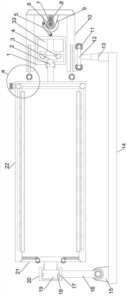
[0022] see Figure 1~3 , in the embodiment of the present invention, a new type of high-efficiency ball mill includes a support mounting plate 14 arranged horizontally, a rotating mounting cylinder 22 is arranged horizontally above the support mounting plate 14, and a support mounting frame is vertically provided at the upper left end of the support mounting plate 14 15. The upper end of the support installation frame 15 is provided with a support swing frame 16 through the rotating shaft, and the upper end of the support swing frame 16 is horizontally provided with a limit rotation sleeve 20, and the middle position of the left end of the rotation installation cylinder 22 cooperates with the limit rotation sleeve 20 to set a limit rotation column 19. The outer side of the limiting rotation column 19 is provided with a rotating conductive groove 18, and the inner side of the limiting rotating sleeve 20 is provided with a rotating conductive ring 17 in cooperation with the rotat...

Embodiment 2

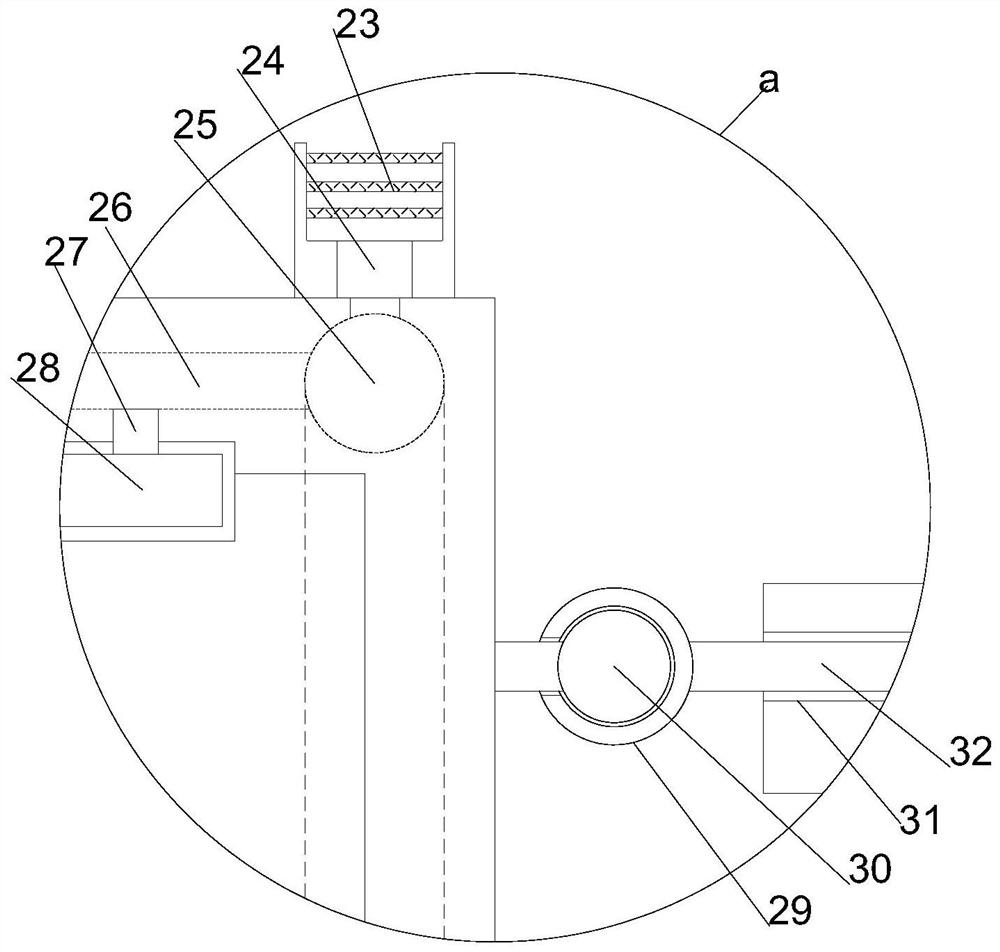
[0025] On the basis of Embodiment 1, while the rotating installation cylinder 22 rotates, the cooperation between the rotating guide cylinder and the rotating installation ring 30 realizes the stable rotation of the rotating installation cylinder 22, while shaking, the orientation guide post 32 and the orientation guide hole Under the cooperation of 31, stable rocking is realized, and finally by the electric control lifting column 13, the tilting of the rotating installation cylinder 22 is realized, discharging is realized, and the ball milling operation is completed.


PUM


Abstract

The invention relates to the field of ball mills, in particular to a novel efficient ball mill. The novel efficient ball mill comprises a horizontally-arranged supporting mounting plate, wherein a rotating mounting cylinder is transversely arranged above the supporting mounting plate, a supporting mounting frame is vertically arranged at the upper left end of the supporting mounting plate, a supporting swing frame is arranged at the upper end of the supporting mounting frame through a rotating shaft, a limiting rotating sleeve is horizontally arranged at the upper end of the supporting swing frame, a limiting rotating column matched with the limiting rotating sleeve is arranged in the middle of the left end of the rotating mounting cylinder, and rotating gates matched with the limiting rotating column are symmetrically arranged at the left end of the rotating mounting cylinder. Through a guide displacement type transmission structure, the ball mill keeps axial shaking in ball milling operation, so that the ball milling efficiency and quality are improved, fluctuation change in the rotating process is achieved through pneumatic control, the ball milling quality and efficiency are further improved, and meanwhile, noise in the ball milling process is reduced, the practical experience of the ball mill is remarkably improved, and the ball mill is suitable for large-scale application and popularization.

Description

technical field [0001] The invention relates to the field of ball mills, in particular to a novel high-efficiency ball mill. Background technique [0002] The ball mill is the key equipment for crushing the material after it is crushed. The ball mill rolls the grinding body in the cylinder and collides with the material, and then grinds the material into powder. The ball mill is widely used in cement, silicate products, refractory materials, chemical fertilizers and Production industries such as glass and ceramics. [0003] In existing ball mills, the ball mill cylinder is usually installed on the support base through bearings, and the drive module is usually installed on one end of the ball mill cylinder. After the drive module works, it drives the ball mill cylinder to rotate. Due to the gravity, the overall rolling of the ball mill roller shakes slightly, and the force is uneven; the existing ring gear is usually exposed on the outer wall of the ball mill roller, because...

Claims


Application Information

Patent Timeline
Patent Type & Authority Applications(China)
IPC IPC(8): B02C17/10B02C17/24
CPCB02C17/10B02C17/24
Inventor 陈希福
Owner 山东环磨机械制造有限公司
Why Eureka
Try Eureka