Parallel type three-degree-of-freedom precision micro-motion mechanism of composite differential branch chain and working method thereof
A parallel-connected, degree-of-freedom technology, applied in piezoelectric effect/electrostrictive or magnetostrictive motors, generators/motors, electrical components, etc., can solve the mechanism's natural frequency drop and ball hinge structure that affects the bearing capacity of the device , the influence of mechanism dynamic characteristics and other issues, to achieve the effect of strong anti-interference ability, good dynamic performance and strong bearing capacity
- Summary
- Abstract
- Description
- Claims
- Application Information
AI Technical Summary
Problems solved by technology
Method used
Image
Examples
Embodiment 1
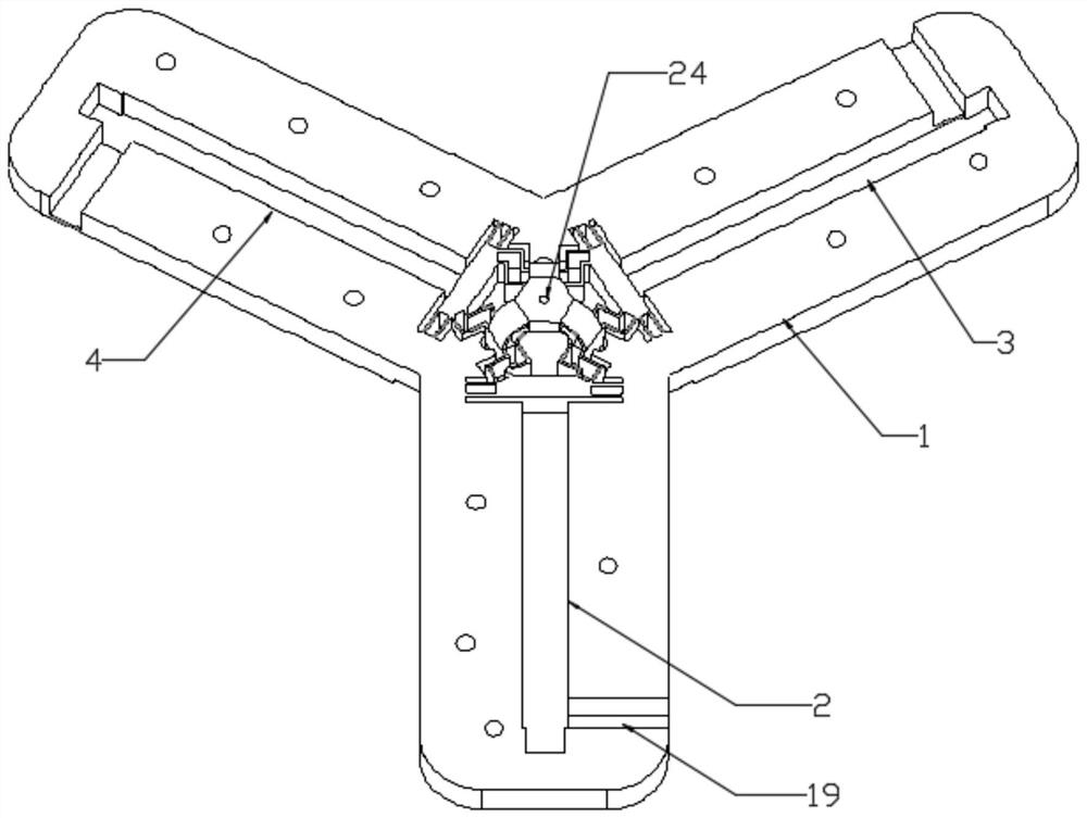
[0041] A parallel three-degree-of-freedom precision micro-motion mechanism of a composite differential branch chain, including three sets of flexible drive units and an output block 24, the output block 24 is located at the center of the three sets of flexible drive units,
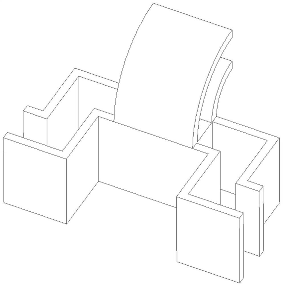
[0042] Each group of flexible driving units includes a piezoelectric ceramic driver and a driving block driven by the piezoelectric ceramic driver, and the two sides of the driving block are respectively positioned by a parallelogram flexible hinge 9 structure, and each adjacent two The edges of each driving block are connected to an intermediate block through a zigzag hinge, and each intermediate block is connected to the output block 24 through a semicircular hinge.
[0043] Preferably, the parallel-connected three-degree-of-freedom precision micro-motion mechanism also includes a frame 1, and three mounting slots are formed on the frame 1, and a piezoelectric ceramic driver is installed in each mounting ...
Embodiment 2
[0057] As described in Example 1, the working mode of the parallel three-degree-of-freedom precision micro-motion mechanism of the composite differential branch chain:
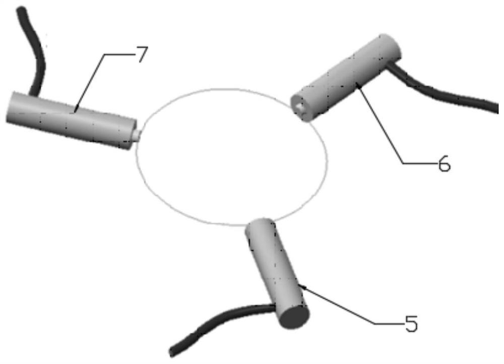
[0058] When the first piezoelectric ceramic driver 5 stretches, and when the second piezoelectric ceramic driver 6 and the third piezoelectric ceramic driver 7 contract according to a certain motion law, the output block 24 moves along the x direction; when the first piezoelectric ceramic driver 5, The third piezoelectric ceramic driver 7 stretches according to a certain motion law, and when the second piezoelectric ceramic driver 6 contracts simultaneously, the output block 24 moves along the y direction; when the first piezoelectric ceramic driver 5, the second piezoelectric ceramic driver 6, When the third piezoelectric ceramic driver 7 expands or contracts simultaneously, the output block 24 moves along the z direction.
Embodiment 3
[0060] 3.1 Static properties
[0061] For the convenience of simulation, the core structure is extracted from the parallel three-degree-of-freedom precision micro-motion mechanism. The thick bottom of the hinge of the three-dimensional vibrating device b=1 mm, and the piezoelectric actuators are arranged perpendicular to the first driving mass 8 , the second driving mass 10 and the third driving mass 11 .
[0062] A voltage is applied to the first driving block 8, and the first driving block 8 moves in the piezoelectric direction. In order to calculate the input stiffness of the device, a force of 100N is applied to the first driving block 8, and the obtained displacement nephogram is as follows Figure 5 shown. The displacement of the first drive block 8 is 28.5 μm, and the input stiffness is 3.509 N / μm. The output block 24 has moved 16.375 μm in the y direction and 4.62 μm in the z direction.
[0063] Apply a force of 100N to the first driving block 8 and the second driv...
PUM
 Abstract
Description
Claims
Application Information
 - Generate Ideas
- Intellectual Property
- Life Sciences
- Materials
- Tech Scout
- Unparalleled Data Quality
- Higher Quality Content
- 60% Fewer Hallucinations
Browse by: Latest US Patents, China's latest patents, Technical Efficacy Thesaurus, Application Domain, Technology Topic, Popular Technical Reports.
© 2025 PatSnap. All rights reserved.Legal|Privacy policy|Modern Slavery Act Transparency Statement|Sitemap|About US| Contact US: help@patsnap.com


