Small-emission-angle front-light-emitting laser

A laser and emission angle technology, applied in the field of lasers, can solve the problems of affecting the optical coupling efficiency and the large angle of light output, and achieve the effects of improving the coupling efficiency, reducing the divergence angle, and improving the cooling effect

Pending Publication Date: 2021-05-28
芯峰光电技术(深圳)有限公司
View PDF4 Cites 0 Cited by
  • Summary
  • Abstract
  • Description
  • Claims
  • Application Information

AI Technical Summary

Problems solved by technology

[0002] Most of the traditional laser chips are edge-divergent chips. The waveguide is on the plane and emits light from the side. When packaging, the chip needs to be vertically attached to the carrier, and the angle of light output is relatively large, which affects the coupling efficiency of light.

Method used


Image

  • Small-emission-angle front-light-emitting laser

Examples


Embodiment Construction

[0008] In order to facilitate the understanding of the present invention, the present invention will be described more fully below with reference to the associated drawings. A preferred embodiment of the invention is shown in the drawings. However, the present invention can be embodied in many different forms and is not limited to the embodiments described herein. Rather, these embodiments are provided so that the disclosure of the present invention will be thorough and complete.

[0009] Unless otherwise defined, all technical and scientific terms used herein have the same meaning as commonly understood by one of ordinary skill in the technical field of the invention. The terms used herein in the description of the present invention are for the purpose of describing specific embodiments only, and are not intended to limit the present invention.

[0010] It should be noted that when an element is referred to as being “fixed” to another element, it can be directly on the othe...


PUM


Abstract

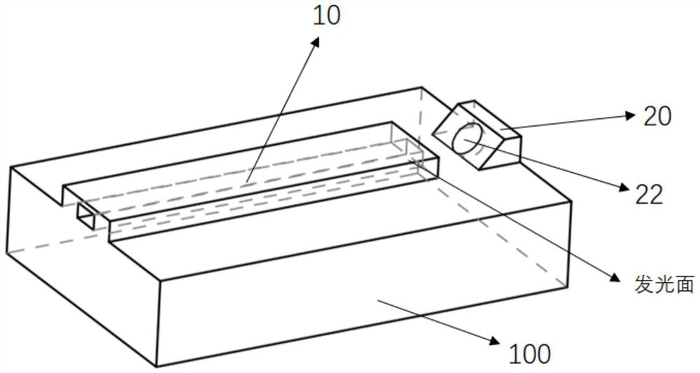
The invention relates to a small-emission-angle front light emitting laser. The small-emission-angle front-light-emitting laser comprises a carrier, an optical waveguide of the laser is attached to the surface of the carrier, the side face of the optical waveguide emits light, and the light emitting direction of the optical waveguide is parallel to the carrier; the surface of the carrier is further provided with an etching reflector, the etching reflector is arranged in the light emitting direction of the optical waveguide, the face, right opposite to the light emitting side face of the optical waveguide, of the etching reflector is a 35-55-degree inclined face, the inclined face is provided with a pit, the surface of the pit is plated with a reflection medium, light emitted by the optical waveguide is emitted to the pit to generate reflection of 80-100 degrees, and the pit reflects the light emitted by the optical waveguide at 80-100 degrees and simultaneously has the effect of focusing the light or the effect of reducing the divergence angle. According to the small-emission-angle front-light-emitting laser, light is focused through reflection of the inclined plane and the pit, the divergence angle can be effectively reduced, and the coupling efficiency is improved.

Description

technical field [0001] The invention relates to the technical field of lasers, in particular to a laser that emits light from the front with a small emission angle. Background technique [0002] Most of the traditional laser chips are edge-divergent chips, the waveguide is on the plane, and the side emits light. When packaging, the chip needs to be vertically attached to the carrier, and the angle of light output is relatively large, which affects the coupling efficiency of light. Contents of the invention [0003] The technical problem to be solved by the present invention is to provide a laser that emits light from the front with a small emission angle and effectively improves the optical coupling efficiency. [0004] For realizing the purpose of the present invention, the present invention adopts following technical scheme: [0005] A laser with a small emission angle that emits light from the front, including a carrier, the surface of the carrier is bonded with an opt...

Claims


Application Information

Patent Timeline
Patent Type & Authority Applications(China)
IPC IPC(8): H01S5/10H01S5/028
CPCH01S5/028H01S5/1082H01S5/1085
Inventor 钟文彪钟文斌
Owner 芯峰光电技术(深圳)有限公司
Why Eureka
Try Eureka