Clutch structure of electric operating mechanism for circuit breaker

A technology of electric operating mechanism and circuit breaker, which is applied in the direction of protection switch operation/release mechanism, etc. It can solve problems such as potential safety hazards, circuit breaker impact, and large operating force of circuit breakers, and achieves suitable for mass production, accurate and reliable action, and consistent structure good sex effect

Pending Publication Date: 2021-05-28
WUXI KAIXUAN MOTOR
View PDF0 Cites 0 Cited by
  • Summary
  • Abstract
  • Description
  • Claims
  • Application Information

AI Technical Summary

Problems solved by technology

[0003] The operating force of the circuit breaker is generally large, and it is difficult for an independent motor to realize the function of electric operation, so the electric operating mechanism is generally composed of a motor and a reduction mechanism, so that a circuit breaker equipped with an electric operating mechanism can realize electric and manual functions, but Since manual operation and electric operation both drive the main shaft of the circuit breaker to realize the corresponding functions, it is extremely inconvenient in actual use and has certain safety hazards; It is necessary to overcome the resistance of the deceleration mechanism; during electric operation, the electric operating mechanism drives the circuit breaker to work. When the main shaft of the circuit breaker rotates to a specific position, the motor is powered off. The motor and the deceleration mechanism cannot stop rotating immediately under inertia, which will cause damage to the circuit breaker. A certain impact may have a certain impact on the performance and mechanical life of the circuit breaker
[0004] In order to solve the above problems, on the basis of the electric operating mechanism, a clutch structure is added to the reduction mechanism. The current clutch structure is large in size and needs to occupy a large space. The structure is complex and there are many transmission relationships between parts, resulting in poor movement accuracy

Method used


Image

  • Clutch structure of electric operating mechanism for circuit breaker
  • Clutch structure of electric operating mechanism for circuit breaker
  • Clutch structure of electric operating mechanism for circuit breaker

Examples


Embodiment Construction

[0022] In order to make the object, technical solution and advantages of the present invention clearer, the present invention will be further described in detail below in conjunction with the accompanying drawings and embodiments. It should be understood that the specific embodiments described here are only used to explain the present invention, not to limit the present invention.

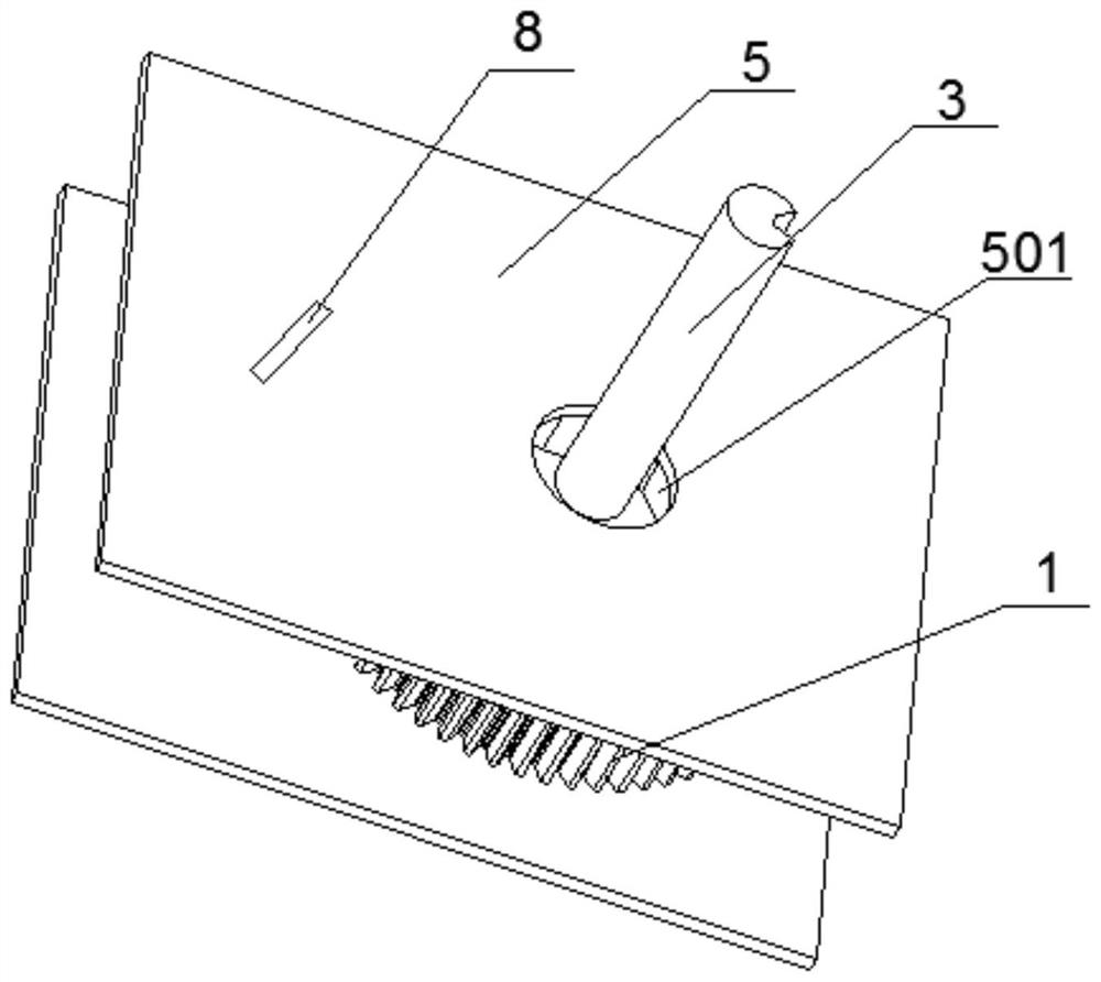
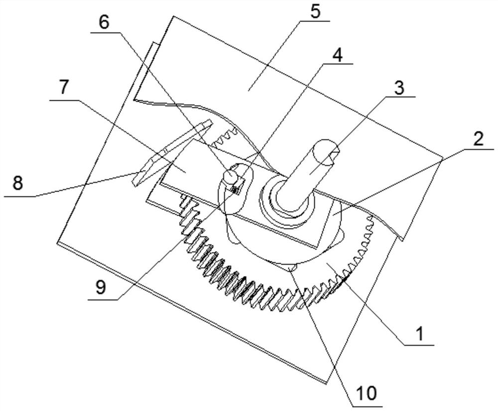
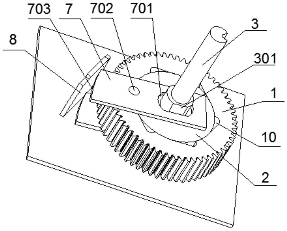
[0023] Please refer to the attached Figure 1-5 , the present invention provides a clutch structure of an electric operating mechanism for a circuit breaker. The entire structure is assembled in a frame 5, including a gear 1, a star wheel 2, a push rod 7 and a top plate 8. The star wheel 2 is coaxially arranged on the gear 1 In the center hole 101 of the star wheel 2, a main shaft 3 is fixed through the star wheel 2, and when the star wheel 2 rotates, the main shaft 3 is driven to rotate; Rod 7; a positioning hole 501 for the main shaft 3 to pass through is provided on the frame 5, and the main sh...


PUM


Abstract

The invention provides a clutch structure of an electric operating mechanism for a circuit breaker, which comprises a gear, a star wheel, push rods and a top plate, wherein the star wheel is coaxially arranged in a center hole of the gear, and the push rods capable of reciprocating in the radial direction of the star wheel are arranged on the two sides of the star wheel in a sleeving mode; a spring is arranged in the star wheel, a stop pin is arranged at the other end of the spring in a telescopic mode, and the two ends of the stop pin and the push rod are fixedly arranged; a plurality of spigots matched with the stop pin are annularly arranged on the outer edge of the center hole, and the stop pin can be switched in the center hole and the spigot; and the top plate is arranged on the outer side of the gear and is fixed in position. The clutch structure is simple, does not occupy external space, is good in action consistency, is more suitable for batch production, realizes clutch on the premise of not increasing axial and radial sizes, and is low in manufacturing cost.

Description

technical field [0001] The invention relates to a circuit breaker accessory, in particular to a clutch structure of an electric operating mechanism for a circuit breaker. Background technique [0002] The circuit breaker is a key component in the process of power grid output, power transformation, and power distribution; when the circuit breaker is working, the circuit can be opened and closed by manual operation, or by electric operation; the electric operating mechanism is to realize the circuit breaker The core component of the machine operation. [0003] The operating force of the circuit breaker is generally large, and it is difficult for an independent motor to realize the function of electric operation, so the electric operating mechanism is generally composed of a motor and a reduction mechanism, so that a circuit breaker equipped with an electric operating mechanism can realize electric and manual functions, but Since manual operation and electric operation both dr...

Claims


Application Information

Patent Timeline
Patent Type & Authority Applications(China)
IPC IPC(8): H01H71/70
CPCH01H71/70
Inventor 牛和强
Owner WUXI KAIXUAN MOTOR
Why Eureka
Try Eureka