


Quick Research
Generate reliable direction feasibility study reports for your R&D in just a few steps.

Technical Q&A
Discover and master advanced knowledge NOW. Basics, ideas, possibilities, all at once.

Find Solutions
As an expert in R&D theories, this can generate solutions to your technical problems instantly.

Evaluate Feasibility
Analyze your overall solution with one click, know your potential R&D risks in advance.

Monitor Landscape
Get weekly tech updates, stay abreast of the latest tech innovations and key insights.
Water storage tank, water storage tank cleaning system and water storage tank cleaning control method
A water storage tank and main controller technology, applied in the field of cleaning, can solve the problems of not being able to detect the quality of stored water in real time, affecting the quality of drinking water for residents, and high water storage tanks, so as to achieve simple and intelligent cleaning methods, eliminate manual safety risks, and improve efficiency effect
- Summary
- Abstract
- Description
- Claims
- Application Information
AI Technical Summary
Problems solved by technology
Method used
Image

Examples
Embodiment 1
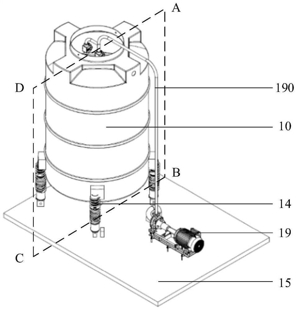
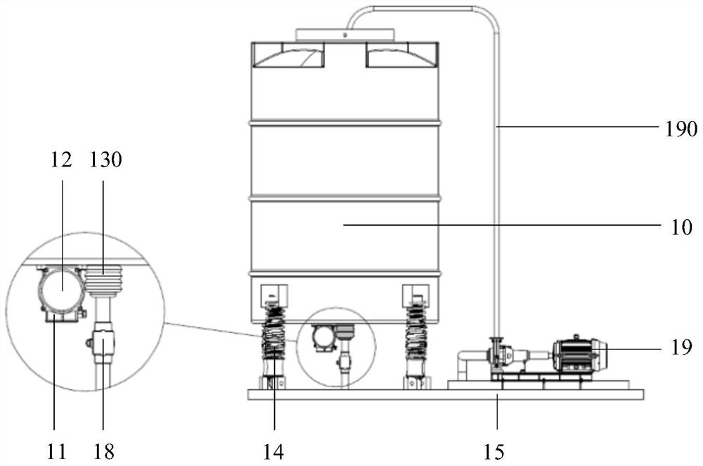
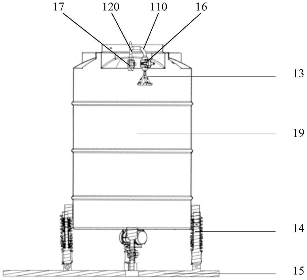
[0033] figure 1 It is a schematic structural diagram of a water storage tank provided in Embodiment 1 of the present invention, figure 2 yes figure 1 side view of the supplied water storage tank, image 3 yes figure 1 A sectional view along the ABCD section of the provided water storage tank. refer to figure 1 , figure 2 and image 3 As shown, the water storage tank includes: a water storage tank body 10, a main controller 11, a water quality sensor (not shown in the figure), a vibrator 12 and a spray device 13; the water quality sensor is arranged inside the water storage tank body 10 The water quality sensor is communicated with the main controller 11, and the water quality sensor is used to detect the water quality information in the water storage tank body 10 in real time; the vibrator 12 is fixedly connected with the water storage tank body 10; Connected, used for spraying and cleaning the water storage tank body 10; both the vibrator 12 and the spraying device 1...
Embodiment 2
[0053] On the basis of the first embodiment above, the second embodiment of the present invention provides a cleaning control method for a water storage tank, which is applicable to the water storage tank described in the first embodiment above, Figure 5 It is a flow chart of a cleaning control method for a water storage tank provided in Embodiment 2 of the present invention. like Figure 5 As shown, the cleaning control method of the water storage tank includes:
[0054] S110. Obtain water quality information in the water storage tank body.
[0055] Items of water quality information may include turbidity of impurities, concentration of particulate matter, and the like. The water storage tank cleaning control method provided by Embodiment 2 of the present invention can detect the water quality information in the water storage tank body in real time, and judge in real time whether each item of water quality information exceeds the corresponding preset water quality paramete...
Embodiment 3
[0062] On the basis of the first embodiment above, the third embodiment of the present invention provides a water storage tank cleaning system, Figure 6 It is a structural block diagram of a water storage tank cleaning system provided in Embodiment 3 of the present invention. like Figure 6 As shown, the water storage tank cleaning system includes the water storage tank 1 described in the first embodiment above, and also includes a mobile terminal 2; the mobile terminal 2 is connected to the water storage tank 1 in communication.
[0063] The mobile terminal 2 can be the water storage tank cleaning control software installed on a mobile phone or a computer. The main controller of the water storage tank 1 may be integrated with a communication module 22 , and the mobile terminal 2 realizes wireless communication with the water storage tank 1 through the communication module 22 . The communication module 22 can be any device with wireless communication. In Embodiment 3 of the...
PUM
 Abstract
Description
Claims
Application Information
 - R&D Engineer
- R&D Manager
- IP Professional
- Industry Leading Data Capabilities
- Powerful AI technology
- Patent DNA Extraction
Browse by: Latest US Patents, China's latest patents, Technical Efficacy Thesaurus, Application Domain, Technology Topic, Popular Technical Reports.
© 2024 PatSnap. All rights reserved.Legal|Privacy policy|Modern Slavery Act Transparency Statement|Sitemap|About US| Contact US: help@patsnap.com