Method for correcting point cloud motion distortion of laser radar

A technology of laser radar and point cloud, which is applied in the direction of radio wave measurement system, measuring device, instrument, etc., can solve the problem of large displacement accumulation error of external sensors, and achieve the effect of enhancing the robustness and stability of the system

Pending Publication Date: 2021-05-28
GUILIN UNIV OF ELECTRONIC TECH
View PDF0 Cites 12 Cited by
  • Summary
  • Abstract
  • Description
  • Claims
  • Application Information

AI Technical Summary

Problems solved by technology

[0005] Aiming at the problem that the external sensor used in the existing correction method for motion distortion of laser radar point cloud has a large displacement accumulation error, the present invention provides a correction method for motion distortion of laser radar point cloud

Method used


Image

  • Method for correcting point cloud motion distortion of laser radar
  • Method for correcting point cloud motion distortion of laser radar
  • Method for correcting point cloud motion distortion of laser radar

Examples


specific Embodiment approach 1

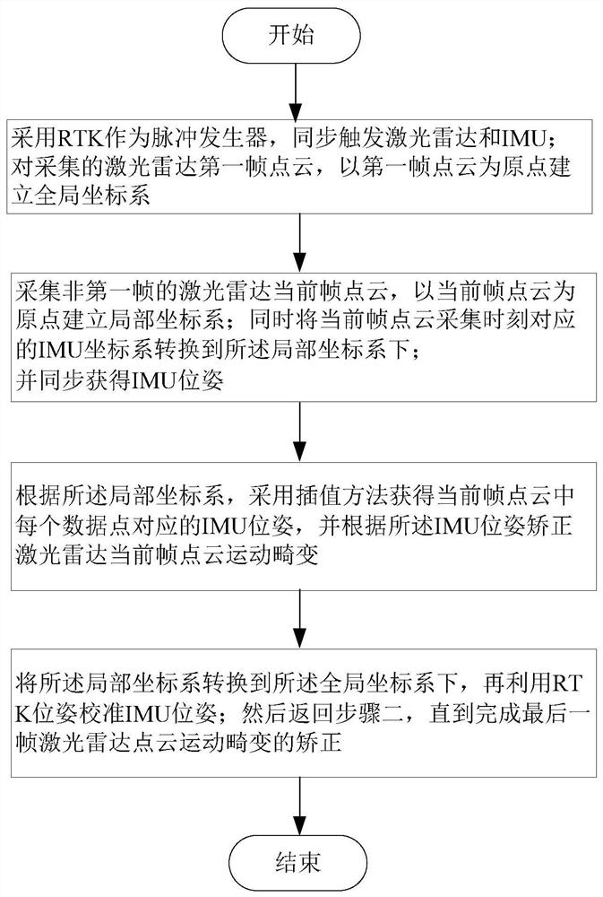
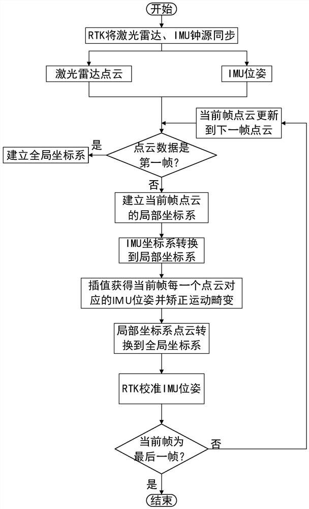
[0047] Specific implementation mode 1. Combination figure 1 and figure 2 As shown, the present invention provides a method for correcting motion distortion of a lidar point cloud, including:

[0048] Step 1: Use RTK as the pulse generator to trigger the lidar and IMU synchronously; for the first frame point cloud of the collected lidar, establish a global coordinate system with the first frame point cloud as the origin; RTK can be triggered after each trigger. Correct the own clock to complete the clock source time synchronization on the hardware;

[0049]Step 2: Collect the point cloud of the current frame of the lidar that is not the first frame, and establish a local coordinate system with the point cloud of the current frame as the origin; at the same time, convert the IMU coordinate system corresponding to the point cloud collection moment of the current frame to the local coordinate system; And synchronously obtain the IMU pose;

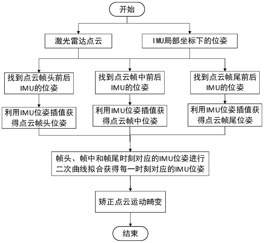
[0050] Step 3: According to the loca...


PUM


Abstract

The invention discloses a laser radar point cloud motion distortion correction method, and belongs to the technical field of unmanned vehicle automatic driving. The method aims at solving the problem that in laser radar point cloud motion distortion correction, the displacement accumulative error of an external sensor is large. The method comprises the following steps: adopting an RTK as a pulse generator, and synchronously triggering a laser radar and an IMU; establishing a global coordinate system for the first frame point cloud of the laser radar; establishing a local coordinate system for non-first frame point clouds; converting the corresponding IMU coordinate system into the local coordinate system; obtaining the IMU pose synchronously; obtaining an IMU pose corresponding to each data point in the point cloud of the current frame by adopting an interpolation method, and correcting the motion distortion of the point cloud of the current frame of the laser radar according to the IMU pose; converting the local coordinate system to the global coordinate system, and calibrating the IMU pose by using the RTK pose; and performing next frame point cloud correction until correction of the last frame laser radar point cloud motion distortion is completed. According to the invention, the robustness and stability of laser radar point cloud correction are enhanced.

Description

technical field [0001] The invention relates to a method for correcting motion distortion of a laser radar point cloud, and belongs to the technical field of automatic driving of an unmanned vehicle. Background technique [0002] With the development of artificial intelligence, lidar has gained widespread attention due to its advantages of high resolution, long range, unaffected by light, and strong anti-interference ability. [0003] In the field of autonomous driving of unmanned vehicles, lidar can establish map information in unknown environments, providing a good foundation for subsequent positioning and navigation, path planning, etc. When the laser radar based on mechanical rotation scanning moves with the unmanned vehicle, its coordinate system changes continuously, which will cause the points in the same frame of point cloud to be not in the same coordinate system and cause motion distortion. Therefore, it is necessary to analyze the acquired point cloud. The data i...

Claims


Application Information

Patent Timeline
Patent Type & Authority Applications(China)
IPC IPC(8): G01S7/497G01C25/00
CPCG01C25/005G01S7/497
Inventor 刘飞周志全邹钰杰屈婧婧柴文静杨起鸣严景琳
Owner GUILIN UNIV OF ELECTRONIC TECH
Why Eureka
Try Eureka