
Hollow flame low-nitrogen burner

A low-nitrogen burner, hollow technology, applied in the direction of burner, gas fuel burner, combustion method, etc., can solve the problems of easy vibration, condensed water, etc.

Pending Publication Date: 2021-05-28
上海四方锅炉集团工程成套股份有限公司 +1
View PDF0 Cites 0 Cited by
  • Summary
  • Abstract
  • Description
  • Claims
  • Application Information

AI Technical Summary

Problems solved by technology

[0003] However, the application of flue gas external circulation has many disadvantages, for example, condensed water will appear in the backflow of flue gas, and the external circulation flue gas mixed into the combustion air will easily cause vibration, etc.

Method used


Image

  • Hollow flame low-nitrogen burner
  • Hollow flame low-nitrogen burner
  • Hollow flame low-nitrogen burner

Examples


Embodiment 1

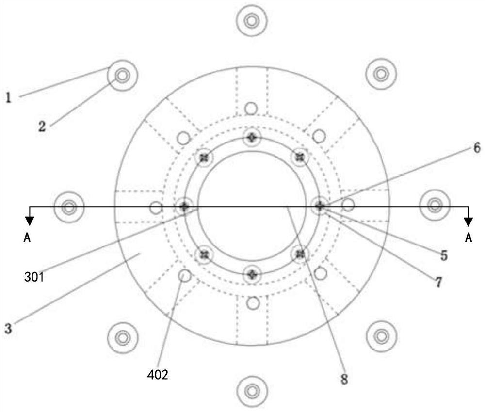
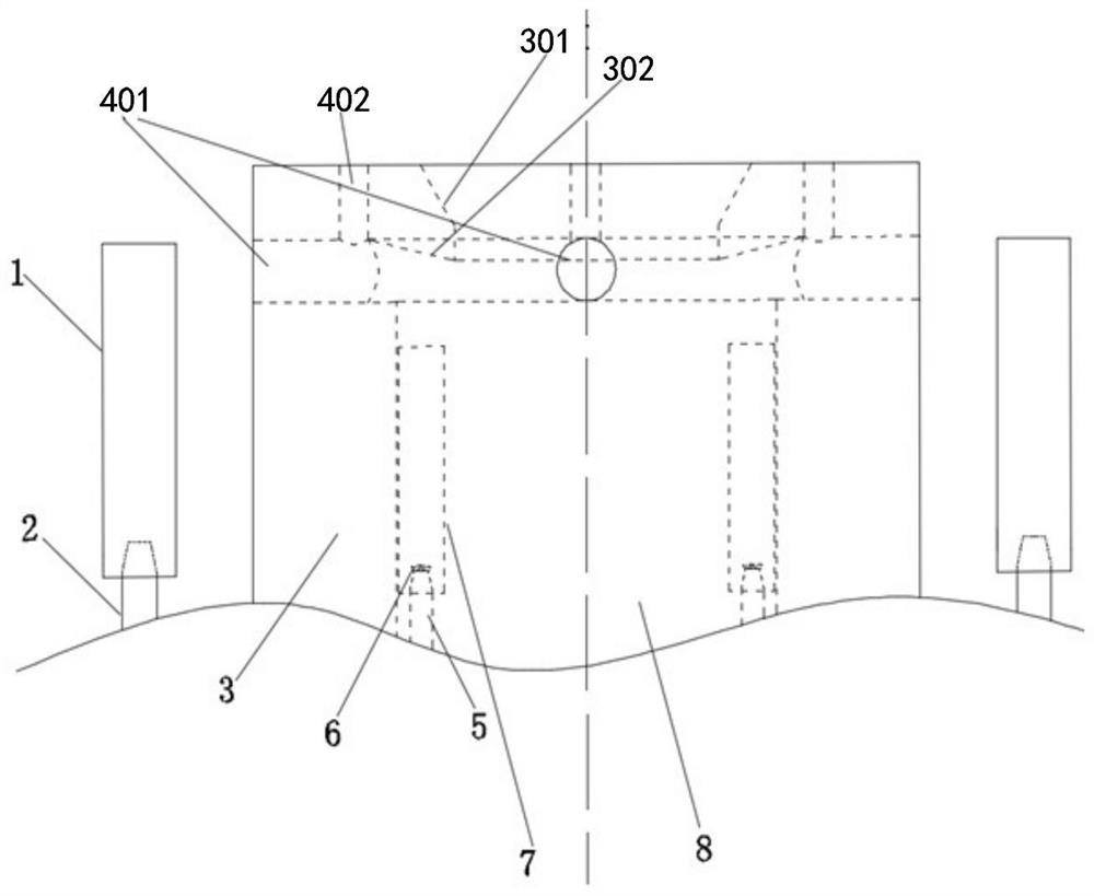
[0034]see Figure 1 to Figure 3 As shown, the present invention provides a hollow flame low-nitrogen burner, including: a casting material platform 3, the casting material platform 3 includes opposite first surfaces and second surfaces, and an air channel is formed inside the casting material platform 3 8. The air channel 8 extends from the first surface to the second surface; the inner gas air channel 7 is located between the air channel 8 and the pouring material table 3, and the inner gas air channel 7 Parallel to the air channel 8; the inner gas channel 5 extends from the first surface to the inner gas air channel 7; the inner gas nozzle 6 is located at the inner gas channel 5 and extends to the inner gas air channel One end in 7; the first flue gas channel 401 of the castable platform is located in the castable platform 3, one end communicates with the air channel 8, and the other end extends to the outer wall of the castable platform 3; the castable platform The second ...

Embodiment 2

[0038] read on Figure 1 to Figure 3 , A hollow flame low nitrogen burner is also provided in this embodiment. Compared with the hollow flame low nitrogen burner in Embodiment 1, the hollow flame low nitrogen burner in this embodiment also includes the following structure:

[0039] As an example, the number of the internal gas air channels 7, the number of the internal gas channels 5, the number of the internal gas nozzles 6, the number of the first flue gas channels 401 of the castable table, the number of the castable table The number of the second flue gas channel 402, the number of the outer gas flue gas mixing channel 1 and the number of the outer gas channel 2 are multiple; the inner gas air channel 7 and the inner gas channel 5 are one by one Correspondingly arranged, a plurality of the internal gas air passages 7 and a plurality of the internal gas passages 5 are arranged at intervals in the circumferential direction with the centerline of the hollow flame low nitrogen...


PUM


Abstract

The invention provides a hollow flame low-nitrogen burner which comprises a castable table, an inner gas air channel, an inner gas channel, an inner gas nozzle, a castable table first smoke channel, a castable table second smoke channel, an outer gas and smoke mixing channel and an outer gas channel. An air channel is formed in the inner side of the castable table. The inner gas air channel is positioned between the air channel and the castable table. The inner gas channel extends into the inner gas air channel from the first surface. The inner gas nozzle is located at the end, extending into the inner gas air channel, of the inner gas channel. The castable table first smoke channel is positioned in the castable table. The castable table second smoke channel is positioned in the castable table. The outer gas and smoke mixing channel is located on the outer side of the castable table. And the outer gas channel is located on the outer side of the castable table and extends into the outer gas and smoke mixing channel from one side of the first surface of the castable table. The castable table has a heat storage function so that the fuel can be stably combusted under the condition that the oxygen content is 0-3%. Due to the special design, no flame is generated in the center of the burner, the low-nitrogen combustion technologies such as premixed combustion, smoke internal circulation and staged combustion are combined, and the effect and stability of low-oxygen combustion are guaranteed.

Description

technical field [0001] The invention relates to the field of boiler and industrial furnace emission reduction, in particular to a hollow flame low-nitrogen burner. Background technique [0002] At present, the nitrogen reduction method commonly used in gas-fired industrial furnaces is low-nitrogen burner plus flue gas external circulation. For boilers burning clean fuels such as natural gas with high calorific value, this nitrogen reduction method can reduce the nitrogen oxide emissions of boilers within Below 30mg / Nm3. At present, most of the low-nitrogen burners on the market use technical methods such as multi-stage combustion and thick-lean combustion to realize nitrogen-reducing combustion; the external circulation of flue gas is to extract a certain proportion of flue gas from the tail of the furnace and then pass it into the combustion chamber through the flue gas circulation pipe. The air inlet of the device is mixed with the combustion-supporting air to participate...

Claims


Application Information

Patent Timeline
Patent Type & Authority Applications(China)
IPC IPC(8): F23D14/04F23D14/46F23D14/64
CPCF23D14/04F23D14/46F23D14/64F23D2900/14
Inventor 马子安刘冰
Owner 上海四方锅炉集团工程成套股份有限公司
Learn More