Quenching heating device and workpiece fixing unit thereof

A technology of fixing unit and heating device, applied in the field of quenching heat treatment

Pending Publication Date: 2021-05-28
XJ ELECTRIC +2
View PDF8 Cites 0 Cited by
  • Summary
  • Abstract
  • Description
  • Claims
  • Application Information

AI Technical Summary

Problems solved by technology

[0004] The purpose of the present invention is to provide a workpiece fixing unit for a quenching heating device, to solve the technical problem in the prior art that the workpiece to be quenched is manually clamped and fixed, resulting in complete dependence on the workers themselves to judge the quenching heating time; the present invention also provides a use The quenching and heating device of the above-mentioned workpiece fixing unit is to solve the technical problem in the prior art that the workpiece to be quenched is manually clamped and fixed, which completely depends on the workers themselves to judge the quenching heating time

Method used


Image

  • Quenching heating device and workpiece fixing unit thereof
  • Quenching heating device and workpiece fixing unit thereof
  • Quenching heating device and workpiece fixing unit thereof

Examples


specific Embodiment 1

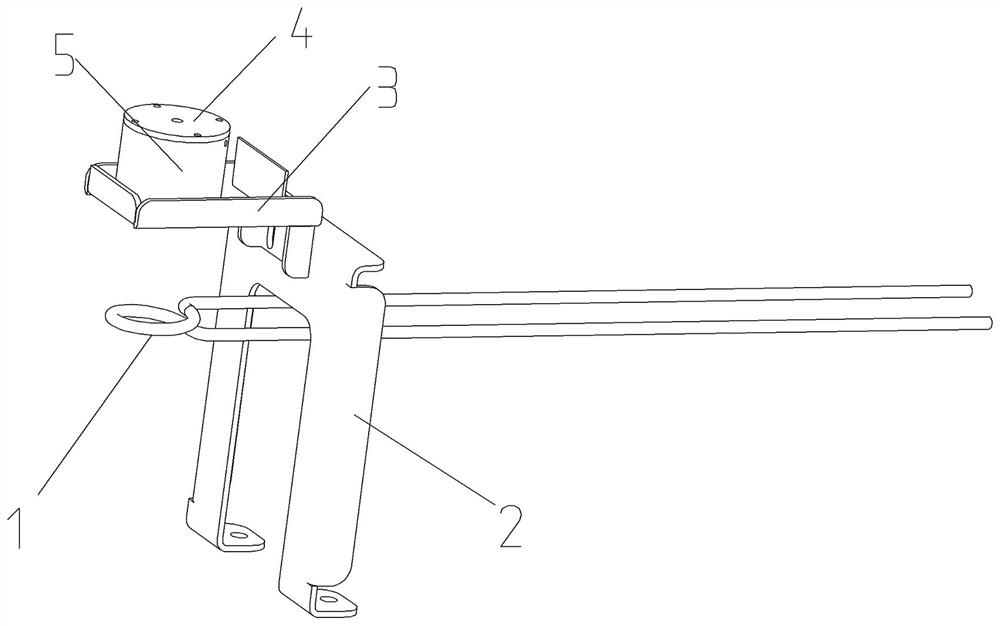
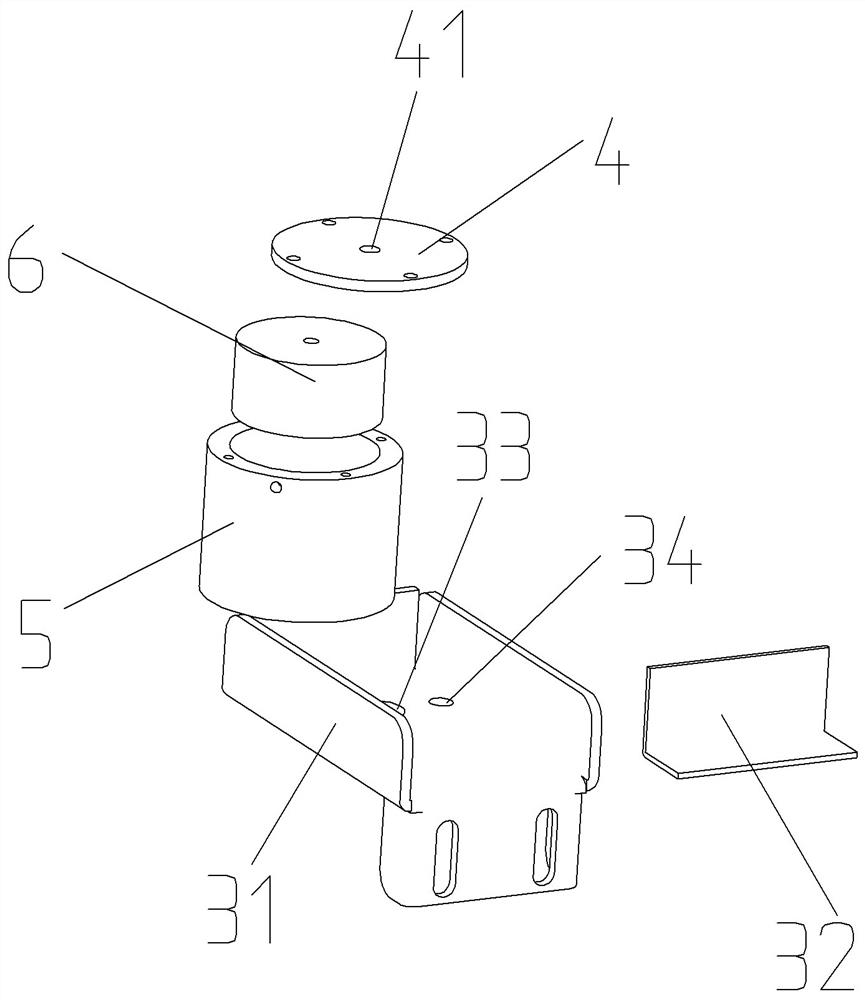
[0058] Such as Figure 1 to Figure 3 As shown, the quenching heating device in this embodiment mainly includes two parts, namely the induction heating coil 1 and the workpiece fixing unit. The workpiece fixing unit is an electromagnetic adsorption fixing structure. The heating coil 1 is absorbed and fixed by the electromagnetic adsorption fixing structure, and the workpiece to be quenched is heated by the induction heating coil 1. After the set heating time, the electromagnetic adsorption structure no longer adsorbs the workpiece to be quenched, and the workpiece to be quenched falls into the corresponding In the quenching liquid tank, it is cooled by the quenching liquid to realize quenching heat treatment.

[0059] In this embodiment, the induction heating coil 1 is a high-frequency coil on the equipment host of the existing quenching equipment, and copper tubes are usually used to meet the frequency requirements of the current loaded on the induction heating coil. After th...

specific Embodiment 2

[0077] It differs from Example 1 mainly in that in the quenching heating device in Example 1, the guide sleeve is cooled by an external water tank. In this example, as Figure 4 with Figure 5 As shown, the guide sleeve 5 itself has an annular groove 11, and the annular groove is used to store cooling liquid for cooling.

[0078] Specifically, the guiding sleeve in this embodiment is the same as the guiding sleeve in Embodiment 1 in that they all have a stepped hole structure, the large diameter section 14 of the stepped hole structure is used to place the electromagnetic chuck, and the small diameter section 11 is used for To guide the assembly of the workpiece to be quenched, it is also necessary to install the corresponding suction cup cover plate to press and fix the electromagnetic chuck during assembly.

[0079] It should be noted that, in this embodiment, the ring groove 11 of the guide sleeve 5 is arranged around the large-diameter section 14 of the stepped hole for c...

specific Embodiment 3

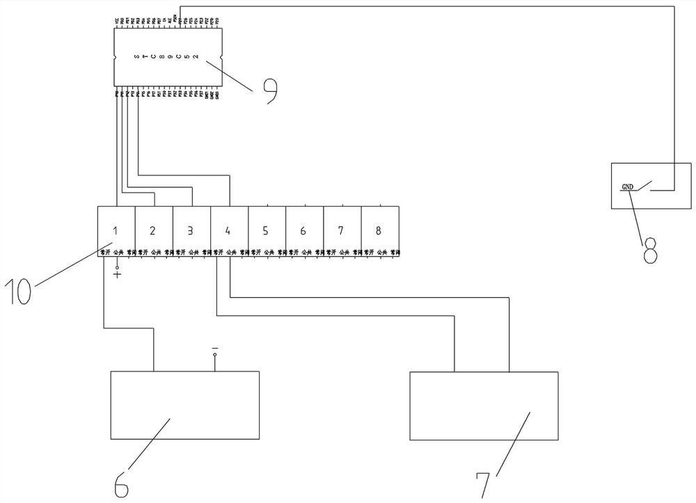
[0084] The main difference between it and Example 1 is that the quenching heating device in Example 1 is modified from the existing quenching equipment. In this embodiment, the quenching heating device is directly integrated on the quenching equipment, that is, the workpiece is directly fixed The unit, button switch and control module are all directly integrated in the quenching equipment.


PUM


Abstract

The invention relates to a quenching heating device and a workpiece fixing unit thereof. The workpiece fixing unit comprises an electromagnetic chuck, a guiding direction and a control module, wherein the electromagnetic chuck is used for being arranged above a corresponding induction heating coil so as to adsorb and fix a to-be-quenched workpiece; the guiding direction of the guiding structure extends in the vertical direction; the guiding structure is used for guiding the to-be-quenched workpiece mounted in the induction heating coil in a penetrating mode to move upwards so that the to-be-quenched workpiece can be adsorbed and fixed by the electromagnetic chuck when the electromagnetic chuck is powered on to work, and guiding the to-be-quenched workpiece to move downwards so as to penetrate through the induction heating coil to fall into quenching liquid when the electromagnetic chuck is powered off; and the control module is used for controlling the electromagnetic chuck to be powered off after the induction heating coil is powered on to heat the to-be-quenched workpiece and set heating time is passed. The control module is used for controlling the electromagnetic chuck to be powered off after the set heating time, so that the heating time can be accurately controlled, the quenching quality can be effectively guaranteed, and the quenching heat treatment effect is improved.

Description

technical field [0001] The invention belongs to the technical field of quenching heat treatment, and in particular relates to a quenching heating device and a workpiece fixing unit thereof. Background technique [0002] When heat treating the workpiece, it is often necessary to quench the parts. If the size of the parts is small, the artificial quenching process is often used for heat treatment. When performing quenching heat treatment, start the quenching equipment, the main engine of the equipment is working, the high-frequency coil is energized, the worker manually clamps the part and puts it into the high-frequency coil, the coil heats the part through induction, and the worker judges whether it is based on experience When the quenching heating temperature is reached, after reaching the heating temperature, the workers throw the parts into the quenching liquid for cooling to realize the quenching heat treatment. [0003] However, in the above-mentioned artificial quench...

Claims


Application Information

Patent Timeline
IPC IPC(8): C21D1/42C21D1/63C21D9/00C21D11/00
CPCC21D1/42C21D1/63C21D9/0062C21D11/00Y02P10/25
Inventor 贾克元唐学芳李召森赵帅兵葛亚龙刘佩宋利卡郑召敏张涛李腾飞
Owner XJ ELECTRIC
Why Eureka
Try Eureka