
Energy-saving and environment-friendly oil tank refueling auxiliary equipment for electromechanical equipment

An energy saving, environmental protection, electromechanical equipment technology, applied in the parts, closures, containers, etc. of bottles/cans, which can solve the problems that affect the normal operation of the equipment, the inability to determine the integrity of the fuel tank, and the inability to regularly replace the oil, so as to avoid excessive oil filling and overflow , convenient for maintenance and ensure the effect of normal operation

Inactive Publication Date: 2021-05-28
杭州砥行机械自动化有限公司
View PDF0 Cites 0 Cited by
  • Summary
  • Abstract
  • Description
  • Claims
  • Application Information

AI Technical Summary

Problems solved by technology

[0003] However, the existing equipment cannot monitor the amount of oil in the fuel tank, and cannot regularly replace the engine oil, so that the normal oil supply efficiency of the equipment fuel tank cannot be guaranteed, which may affect the normal operation of the equipment, and it cannot detect oil leakage well, so it cannot Determine the integrity of the fuel tank; therefore, those skilled in the art provide a kind of energy-saving and environment-friendly fuel tank refueling auxiliary equipment used for electromechanical equipment, to solve the problems raised in the above-mentioned background technology

Method used


Image

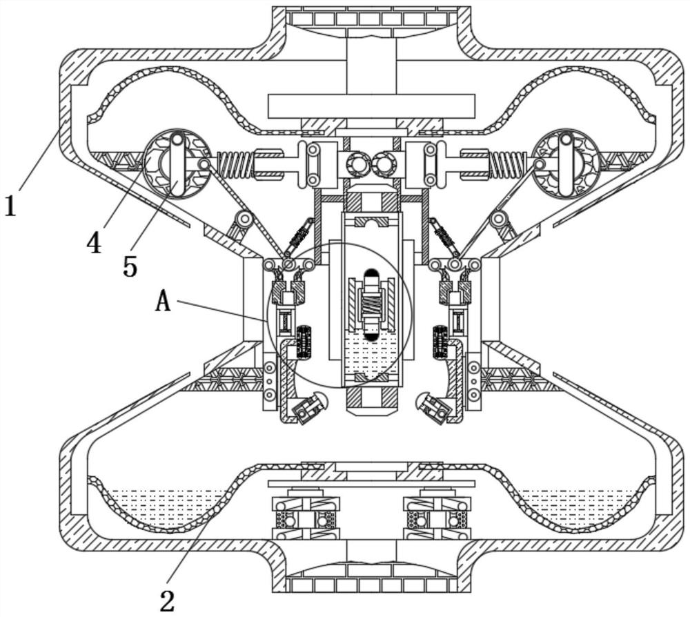
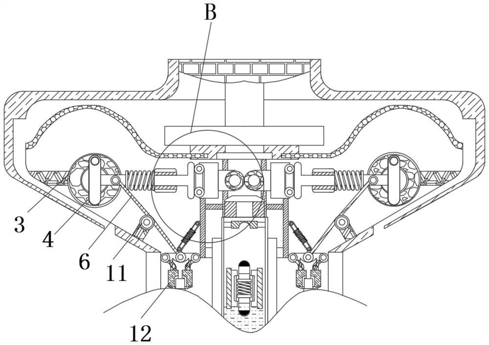
  • Energy-saving and environment-friendly oil tank refueling auxiliary equipment for electromechanical equipment
  • Energy-saving and environment-friendly oil tank refueling auxiliary equipment for electromechanical equipment
  • Energy-saving and environment-friendly oil tank refueling auxiliary equipment for electromechanical equipment

Examples


Embodiment Construction

[0020] The following will clearly and completely describe the technical solutions in the embodiments of the present invention with reference to the accompanying drawings in the embodiments of the present invention. Obviously, the described embodiments are only some, not all, embodiments of the present invention. Based on the embodiments of the present invention, all other embodiments obtained by persons of ordinary skill in the art without making creative efforts belong to the protection scope of the present invention.

[0021] see Figure 1-5 , an energy-saving and environment-friendly fuel tank auxiliary equipment used for electromechanical equipment, including a work frame 1, the inside of the work frame 1 is provided with a chute matching the size of the fixed frame 14, and the upper end of the return spring 13 is in contact with the work frame 1 The inner wall of the working frame 1 is fixedly connected, the inner bottom surface of the working frame 1 is fixedly connected...


PUM


Abstract

The invention relates to the technical field of electromechanical oil tank refueling equipment, in particular to energy-saving and environment-friendly oil tank refueling auxiliary equipment for electromechanical equipment. The auxiliary equipment comprises a working frame, a recovery tank is fixedly connected to the inner bottom surface of the working frame, a positioning rotating wheel is rotationally connected into the working frame through a shaft, a sliding rotating wheel is inserted into the positioning rotating wheel, a transmission rod is movably connected to the front surface of the sliding rotating wheel through a shaft, a traction rope is fixedly connected to the front surface of the transmission rod, a fixed sliding rail is fixedly connected to the position, located outside the transmission rod, in the working frame, a baffle plate is used for shielding an oil filling port, and oil injection is automatically stopped, so that the oil quantity of an oil tank in the equipment can be guaranteed, meanwhile, excessive oil injection overflow is avoided, normal operation of the equipment can be well guaranteed, and the oil injection monitoring effect is achieved, and whether the oil tank is damaged or not can be well judged by shifting an ammeter outside the equipment, so that timely maintenance is facilitated.

Description

technical field [0001] The invention relates to the technical field of electromechanical oil tank refueling equipment, in particular to an energy-saving and environment-friendly auxiliary fuel tank refueling equipment used for electromechanical equipment. Background technique [0002] With the continuous improvement of people's living standards, people's demand for electromechanical equipment in daily life is increasing. From transportation to various household appliances, computers, printers, etc., electromechanical products have become indispensable in people's lives. Electromechanical equipment Generally refers to machinery, electrical appliances, and electrical automation equipment. In construction, it refers to the collective name of machinery and pipeline equipment other than geotechnical engineering, woodworking, steel bars, and muddy water. It is different from hardware and refers to finished products that can achieve certain functions. [0003] However, the existin...

Claims


Application Information

Patent Timeline
IPC IPC(8): B65D43/26B65D79/02
CPCB65D43/26B65D79/02B65D2203/00
Inventor 舒健
Owner 杭州砥行机械自动化有限公司
Learn More