Constant-torque type automobile steering knuckle arm

An automobile steering knuckle and constant torque technology, which is applied to steering mechanisms, steering rods, vehicle components, etc., can solve problems such as difficult steering and increased steering load

Inactive Publication Date: 2021-05-28
孙洪春
View PDF9 Cites 2 Cited by
  • Summary
  • Abstract
  • Description
  • Claims
  • Application Information

AI Technical Summary

Problems solved by technology

[0002] The steering knuckle arm realizes the steering of the two guide wheels by controlling the swing of the two trapezoidal arms, and its input end is connected to one end of the steering straight rod. The pivoting arm of the str...

Method used


Image

  • Constant-torque type automobile steering knuckle arm
  • Constant-torque type automobile steering knuckle arm
  • Constant-torque type automobile steering knuckle arm

Examples


Embodiment 1

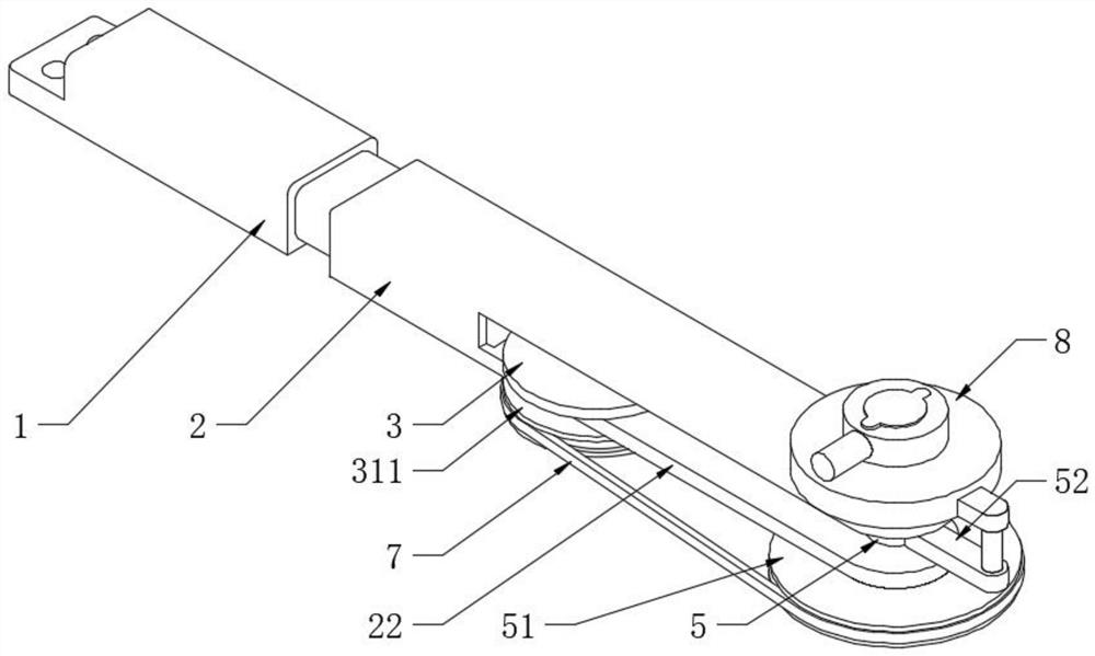
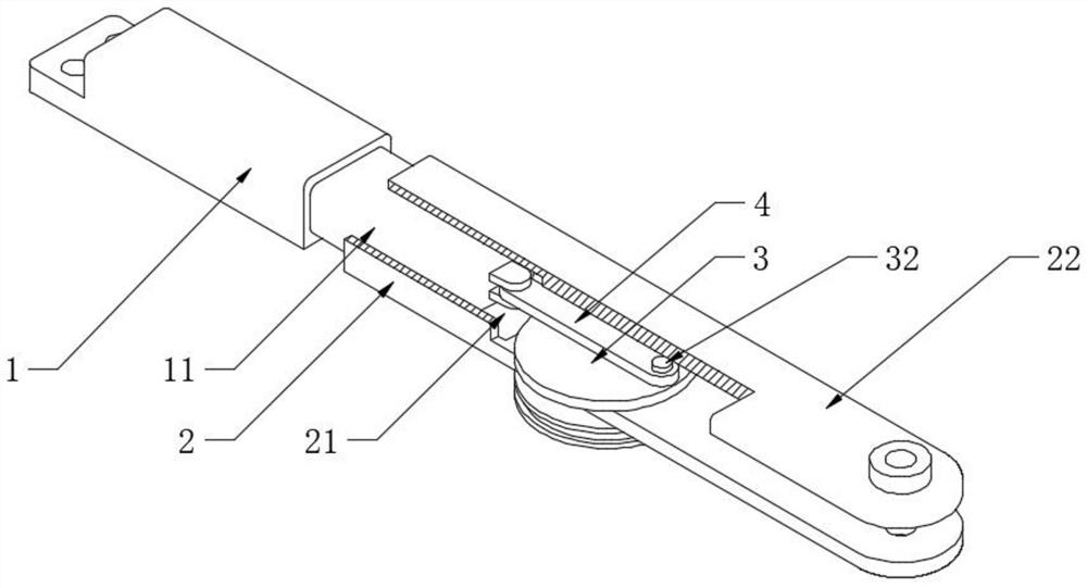
[0030] see Figure 1-4 , a constant torque type automobile steering knuckle arm, including a front arm 1 and a rear arm 2, the forearm 1 is used to be fixedly connected to one of the trapezoidal arms, one end of the forearm 1 is fixedly provided with a guide plate 11, and one end of the rear arm 2 is opened There is a guide hole 21 slidingly matched with the guide plate 11, the forearm 1 and the rear arm 2 are slidingly fitted, the arm plate composed of the two can be extended or shortened, and the other end of the rear arm 2 is fixedly provided with two positioning points distributed parallelly up and down. Plate 22, a transmission turntable 3 is arranged between the two positioning plates 22, and one side of the transmission turntable 3 is fixedly provided with a transmission shaft 31 that is distributed with the same axis and runs through a positioning plate 22 located at the lower part and is rotationally matched. The other side of 3 is fixedly provided with a transmission...

Embodiment 2

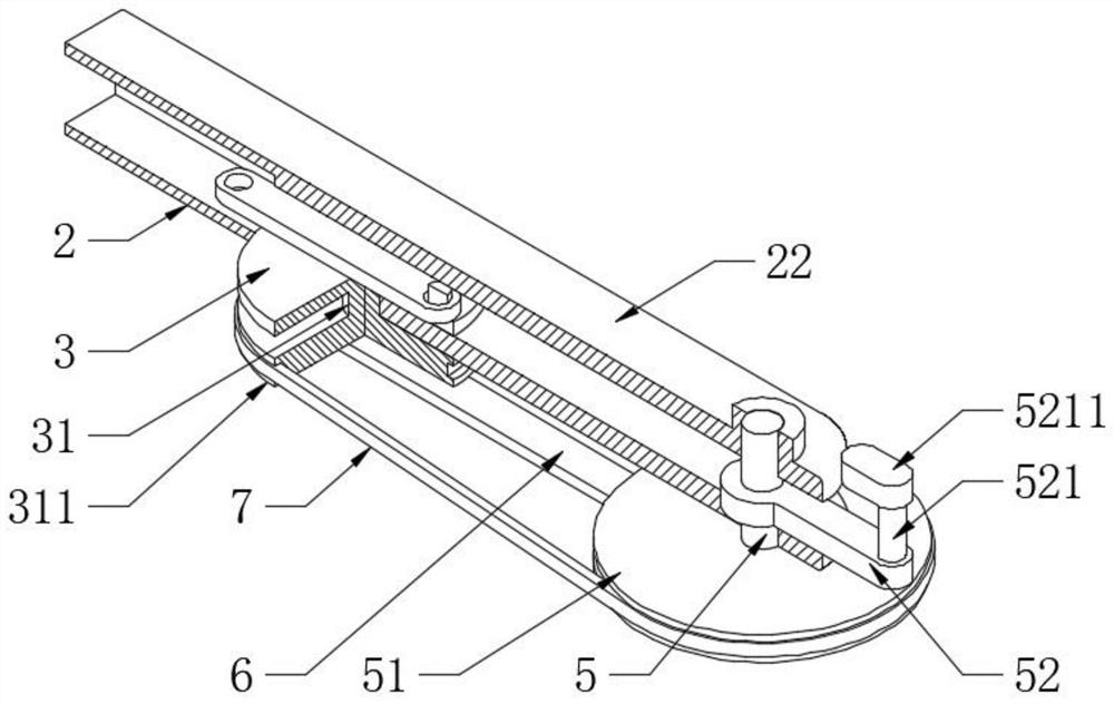
[0032] see Figure 5 The difference from Embodiment 1 is that the other end of the drive shaft 5 passes through another positioning plate 22 and is rotatably connected with a concentrically distributed connecting round table 8, the outer wall of the connecting round table 8 is fixedly connected with one end of the docking block 5211, The upper end surface of the round platform 8 is connected with an anti-shock connecting sleeve 9, that is to say, when turning, the steering wheel will swing, and the forearm 1 will swing correspondingly, which will change the angle between the forearm 1 and the steering rod. This swing will change the state that the forearm 1 protrudes relative to the rear arm 2, and the forearm 1 and the rear arm 2 can be locked by setting the anti-shock connecting sleeve 9. Specifically, the upper end surface of the connecting round table 8 is fixedly provided with a coaxial distribution. The shaft 81, the anti-shock connecting sleeve 9 and the matching shaft ...


PUM


Abstract

The invention discloses a constant-torque type automobile steering knuckle arm which comprises a front arm and a rear arm, a guide plate is fixedly arranged at one end of the front arm, a guide hole in sliding fit with the guide plate is formed in one end of the rear arm, and an upper positioning plate and a lower positioning plate which are distributed in parallel are fixedly arranged at the other end of the rear arm. The front arm and the rear arm are arranged and matched in a telescopic mode, the transmission rotating disc and the driving shaft which are used for controlling the front arm to stretch out and draw back are rotationally connected into the rear arm, the lower driving disc is arranged at one end of the driving shaft, and the lower portion of the transmission rotating disc is connected with the lower transmission disc. The lower driving disc is used for controlling the lower trnamission disc to rotate A for realizing extension or retreating action of the knuckle arm composed of the front arm and the rear arm; a connecting rod is fixedly arranged on the outer surface wall of the driving shaft, the connecting rod is used for being fixedly connected with one end of an external steering straight pull rod, and the included angle between the steering straight pull rod and the rear arm can be changed when the steering straight pull rod moves. Meanwhile, the knuckle arm is driven to extend, and constant-rotating arm steering control is achieved.

Description

technical field [0001] The invention relates to the technical field of automobile steering arms, in particular to a constant torque type automobile steering knuckle arm. Background technique [0002] The steering knuckle arm realizes the steering of the two guide wheels by controlling the swing of the two trapezoidal arms, and its input end is connected to one end of the steering straight rod. The swivel arm of the straight tie rod relative to the swing center of the trapezoidal arm will change, specifically as the steering angle increases, the swivel arm will gradually decrease, thereby increasing the steering load, resulting in difficult steering. [0003] For this reason, the invention provides a constant torque type automobile steering knuckle arm. Contents of the invention [0004] The purpose of the present invention is: in order to solve the problems mentioned in the background technology, a kind of constant torque type automobile steering knuckle arm is proposed. ...

Claims


Application Information

Patent Timeline
IPC IPC(8): B62D7/18
CPCB62D7/18
Inventor 孙洪春
Owner 孙洪春
Why Eureka
Try Eureka