High-speed, precise and lightweight isostatic pressing flexible mold locking mechanism and method of injection machine

An injection machine, lightweight technology, applied in the field of static pressure flexible clamping mechanism, can solve the problems of large weight of clamping system, large impact load, large mold inertia, etc., and achieve simple structure, small impact load, and mold inertia. small effect

Active Publication Date: 2021-05-28
SOUTH CHINA UNIV OF TECH
View PDF15 Cites 0 Cited by
  • Summary
  • Abstract
  • Description
  • Claims
  • Application Information

AI Technical Summary

Problems solved by technology

After the mold is clamped in place, the locking of the mold is realized through the amplification of the toggle force. This mold locking structure mainly relies on the deformation of the tie rod and the template to realize the mold locking. When the tonnage is large, the weight of the mold locking system is quite large and cannot achieve high speed. Precision mode locking
Compared with the three-platen type, the mold clamping device of the two-platen injection machine omits the rear template, reduces the quality of the mold clamping device, and improves the speed of mold clamping. However, the two-platen injection machine not only has a complicated mold clamping structure, but also directly acts On the template of the fixed mold, the template is easily deformed, and the precise mold locking of the injection machine cannot be realized
[0003] Existing injection machines generally improve the precision of mold clamping by improving the rigidity and machining accuracy of the template. However, due to the limitation of the template structure, the bending deformation of the template is too large in this method, and the improvement of precision is limited to a certain extent. The high-rigidity formwork has complex structure, heavy weight, large mold-moving inertia, and large impact load, so high-speed mold clamping cannot be realized
The patent with the publication number CN2880459Y proposes a high-speed and high-precision hydraulic mold clamping device, which mainly realizes high-speed and high-precision hydraulic mold clamping by changing the mechanical structure design between the high-speed mold clamping cylinder and the high-pressure mold clamping cylinder, but this clamping device The internal structure of the clamping cylinder used is complex, and the requirements for the hydraulic system are high, and the existing hydraulic system is difficult to meet its requirements
Therefore, the existing injection machines cannot realize high-speed and precise mold locking at the same time
[0004] In addition, the mold clamping device of the injection machine has certain basic requirements for the space position when installing the mold and taking out the product, while the distance between the tie rods used as supporting and guiding members in the mold clamping device of the conventional injection machine limits the overall size of the mold and also gives Disassembly and repositioning of the mold is inconvenient

Method used


Image

  • High-speed, precise and lightweight isostatic pressing flexible mold locking mechanism and method of injection machine
  • High-speed, precise and lightweight isostatic pressing flexible mold locking mechanism and method of injection machine
  • High-speed, precise and lightweight isostatic pressing flexible mold locking mechanism and method of injection machine

Examples


Embodiment 1

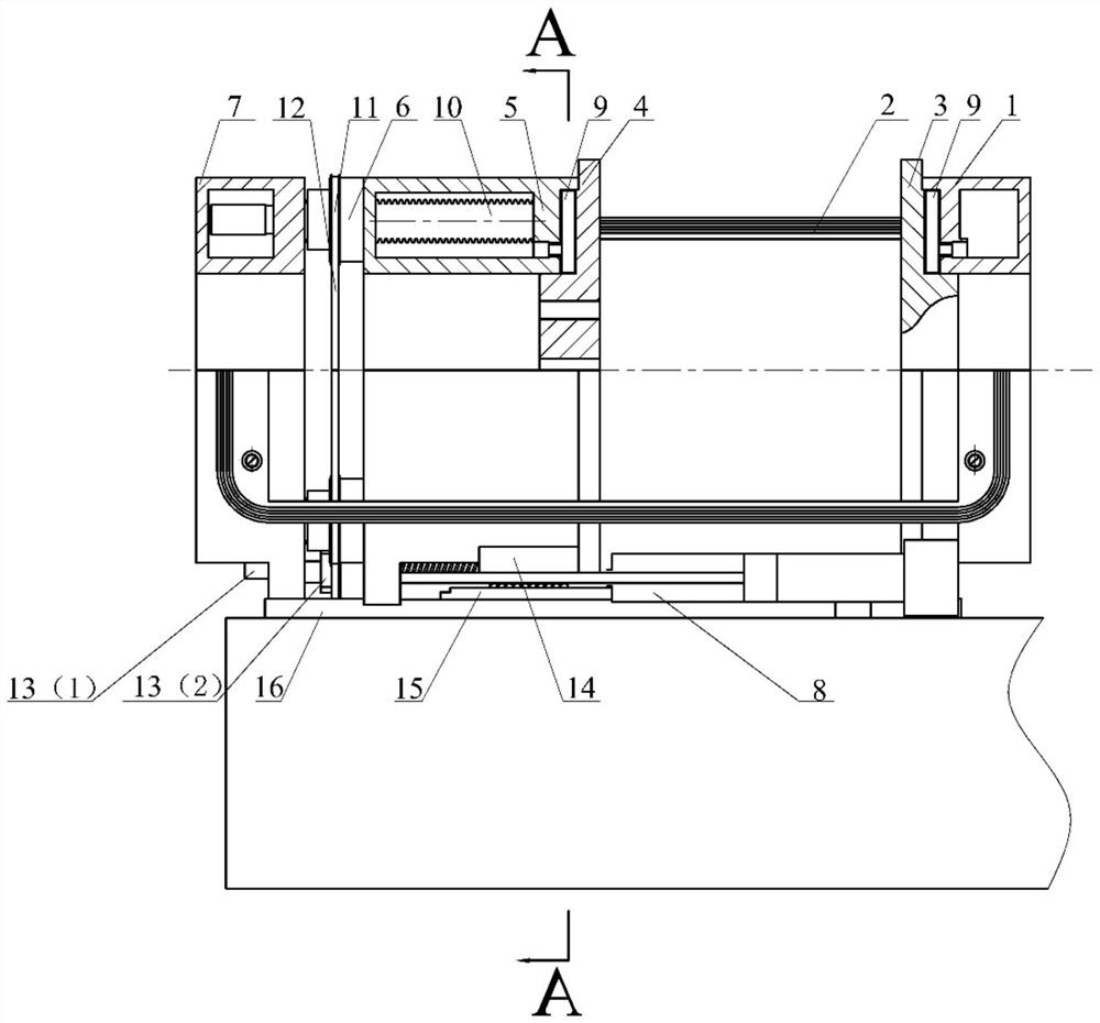
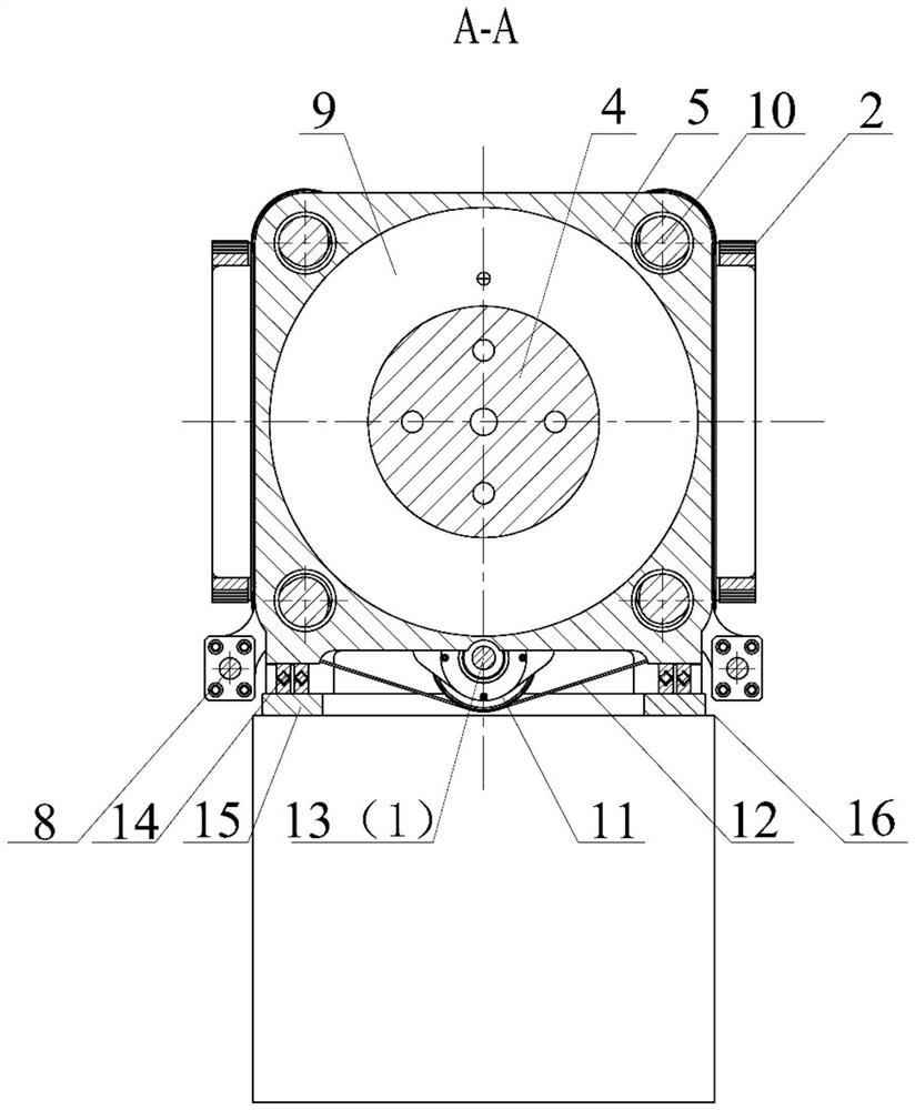
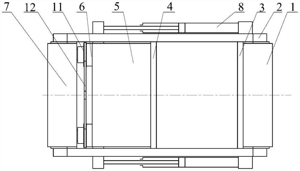
[0034] In this embodiment, a lightweight isostatic flexible mold clamping mechanism for a high-speed precision injection machine, such as Figure 1-3 As shown, it includes a fixed mold support plate 3, a fixed mold static pressure support seat 1, a movable mold support plate 4, a dynamic mold static pressure support seat 5 and a mold locking positioning seat 7, and the fixed mold support plate and the movable mold support plate are opposite to each other. Set, a liquid-filled capsule 9 is provided between the fixed mold support plate and the fixed mold static pressure support seat, a liquid-filled capsule 9 is provided between the movable mold support plate and the dynamic mold static pressure support seat, and the dynamic mold static pressure support seat Located on the moving assembly, the clamping positioning seat is located outside the static pressure support seat of the dynamic mold, and a synchronous follower device for axial positioning is provided between the static pre...

Embodiment 2

[0049] In this embodiment, a lightweight isostatic flexible mold clamping mechanism for a high-speed precision injection machine, such as Figure 4-6 As shown, the difference from Embodiment 1 is that a brake nut 17 for axial positioning is provided between the static pressure support seat of the dynamic mold and the mold locking positioning seat, and the dynamic mold positioning seat is provided on the mold locking positioning seat. A screw pile, wherein the dynamic mold positioning screw pile passes through the static pressure support seat of the dynamic mold. Among them, there are 4 moving mold positioning screw piles, which are respectively installed at the four corners of the mold locking positioning seat. The brake nut is installed on the static pressure support seat of the dynamic mold, and the brake nut is correspondingly provided with a brake oil cylinder, and the brake nut is driven by the brake oil cylinder to tightly hold the dynamic mold positioning screw pile to ...


PUM


Abstract

The invention discloses a high-speed, precise and lightweight isostatic pressing flexible mold locking mechanism and method of an injection machine. The mechanism comprises a fixed mold supporting disc, a fixed mold static pressing supporting seat, a movable mold supporting disc, a movable mold static pressing supporting seat and a mold locking positioning seat, wherein the fixed mold supporting disc and the movable mold supporting disc are oppositely arranged; a liquid filling capsule is arranged between the fixed mold supporting disc and the fixed mold static pressing supporting seat; a liquid filling capsule is arranged between the movable mold supporting disc and the movable mold static pressing supporting seat; the movable mold static pressing supporting seat is located on a moving component; the mold locking positioning seat is located at the outer side of the movable mold static pressing supporting seat; an axial positioning component is arranged between the movable mold static pressing supporting seat and the mold locking positioning seat; and the mold locking positioning seat and the fixed mold static pressing supporting seat are connected through a strip steel overlapping lock. During mold locking, the liquid filling capsule supplements high-pressure oil, so that the fixed mold supporting disc and the movable mold supporting disc are slightly close to each other and the mold is locked, and during mold opening, the liquid filling capsule drains oil, the fixed mold supporting disc and the movable mold supporting disc are slightly away from each other and the mold is unlocked.

Description

technical field [0001] The invention relates to the technical field of mold clamping equipment used in injection machines, in particular to a lightweight isostatic flexible mold clamping mechanism and method for high-speed precision injection machines. Background technique [0002] The mold clamping device of the injection machine is a component that ensures the reliable opening and closing of the molding mold and ejects the product. The clamping device of the traditional injection machine is divided into three-platen type and two-platen type. The mold clamping device of the three-plate injection machine is composed of a movable platen, a fixed platen, a rear platen and a tie rod, etc. The clamping cylinder fixed on the rear platen or the servo motor drives the movable platen to open and close the mold. After the mold is clamped in place, the locking of the mold is realized through the amplification of the toggle force. This mold locking structure mainly relies on the defor...

Claims


Application Information

Patent Timeline
Patent Type & Authority Applications(China)
IPC IPC(8): B29C45/67
CPCB29C45/67B29C45/6778B29C2045/6757
Inventor 瞿金平
Owner SOUTH CHINA UNIV OF TECH
Why Eureka
Try Eureka