Cardiology department safe medical stretcher with wide application range
A kind of applicable scope and cardiology technology, applied in the medical field, can solve problems such as stretcher length and width adjustment, patient bumps, seriousness, etc., achieve good shock resistance, reduce bumps, and have strong applicability
- Summary
- Abstract
- Description
- Claims
- Application Information
AI Technical Summary
Problems solved by technology
Method used
Image
Examples
Embodiment 1
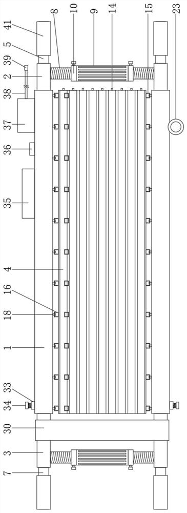
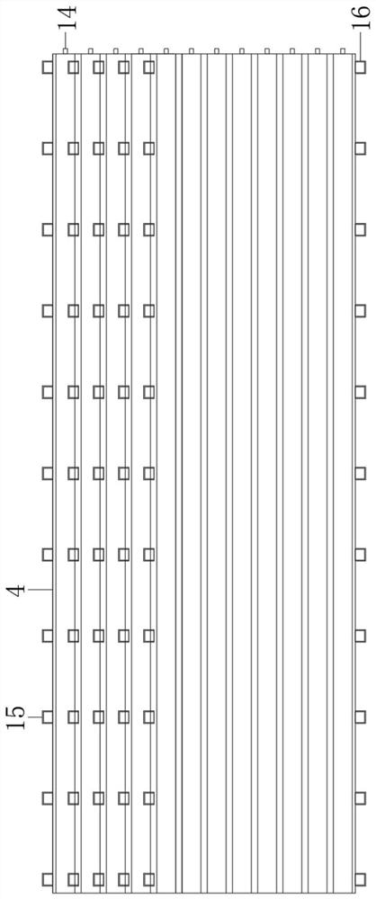
[0042] see Figure 1-9 , the cardiology safety medical stretcher with a wide range of application includes a main pole 1, a fixed auxiliary pole 2, a telescopic auxiliary pole 3 and an inflatable cushion 4, the number of the main poles 1 is two and arranged parallel to each other, the main pole 1 One end is fixedly provided with a fixed sub-rod 2, and the end of the fixed sub-rod 2 away from the main rod 1 is fixed with a first handle 5, and the other end of the main rod 1 is provided with a sliding cavity 6, and the sliding cavity 6 are slidingly provided with telescopic sub-rods 3, and the end of the telescopic sub-rods 3 away from the main rod 1 is fixed with a second handle 7, between the fixed sub-rods 2 and between the telescopic sub-rods 3 All are equipped with a width adjustment device, the width adjustment device includes a first threaded rod 8, a first threaded cylinder 9, a fixed ring 10, a second threaded cylinder 11 and a first locking bolt 12, the fixed sub-rod 2...
Embodiment 2
[0045] see figure 2 , 3 and 9, for the first threaded mandrel 8, both sides of the first threaded mandrel 8 are provided with limiting grooves 40 matching the first locking bolt 12; for the first connecting cloth belt 15 , the first connection tape 15 and the second connection tape 16 are all arranged in a C-shaped structure, and both ends of the first connection tape 15 and the second connection tape 16 are connected to the Inflatable cushion 4 is fixedly connected.
[0046] Through the above scheme of the present invention, the limit groove 40 can cooperate with the first locking bolt 12 to limit the first screw rod 8 and the first threaded cylinder 9, and when the first locking bolt 12 is tightened until the first locking bolt 12 After extending into the limiting groove 40, the first threaded barrel 9 will not rotate again.
Embodiment 3
[0048] see figure 1 and 6 , for the first handle 5 and the second handle 7, the outer walls of the first handle 5 and the second handle 7 are fixedly provided with anti-slip sleeves 41; for the telescopic sub-rod 3, the telescopic sub-rod 3 is away from The outer wall of one end of the first handle 5 is fixedly covered with a first limit ring 42 , and the inner wall of one end of the sliding chamber 6 close to the first handle 5 is fixed with a second limit ring 42 that matches the first limit ring 42 . Ring 43.
[0049] Through the above scheme of the present invention, the anti-slip sleeve 41 can increase the anti-skid performance of the outer walls of the first handle 5 and the second handle 7, and the limiting effect of the first limit ring 42 and the second limit ring 43 can make the telescopic sub-rod 3 not Detach from the sliding chamber 6.
PUM
 Abstract
Description
Claims
Application Information
 - Generate Ideas
- Intellectual Property
- Life Sciences
- Materials
- Tech Scout
- Unparalleled Data Quality
- Higher Quality Content
- 60% Fewer Hallucinations
Browse by: Latest US Patents, China's latest patents, Technical Efficacy Thesaurus, Application Domain, Technology Topic, Popular Technical Reports.
© 2025 PatSnap. All rights reserved.Legal|Privacy policy|Modern Slavery Act Transparency Statement|Sitemap|About US| Contact US: help@patsnap.com


