Connecting terminal

A technology for connecting terminals and male terminals, which is applied in the field of connecting terminals that can prevent arcing, can solve the problems of easy failure of the protective layer and increased production costs, and achieve the effects of low cost and simple structure

Active Publication Date: 2021-05-25
GUOCHUANG INNOVATION CENTER OF MOBILE ENERGY (JIANGSU) CO.,LTD.
View PDF3 Cites 0 Cited by
  • Summary
  • Abstract
  • Description
  • Claims
  • Application Information

AI Technical Summary

Problems solved by technology

[0003] The invention provides a connecting terminal, which solves the problem that the protective layer is easy to fail by setting a physical interlayer to prevent arcing; the problem of increasing the production cost due to the need to increase the control program and switch elements to control the arcing through the circuit, through mechanical movement Instead of the electronic control signal to realize the anti-arc function, the structure is simple and the cost is low

Method used


Image

  • Connecting terminal
  • Connecting terminal
  • Connecting terminal

Examples


Embodiment Construction

[0034] Embodiments of the present invention are described in detail below, examples of which are shown in the drawings, wherein the same or similar reference numerals designate the same or similar elements or elements having the same or similar functions throughout. The embodiments described below by referring to the figures are exemplary only for explaining the present invention and should not be construed as limiting the present invention.

[0035] In addition, it should be noted that the use of words such as "first" and "second" to define components is only for the convenience of distinguishing corresponding components. To limit the protection scope of the present invention.

[0036] The relative arrangements of components and steps, numerical expressions and numerical values ​​set forth in these embodiments do not limit the scope of the present invention unless specifically stated otherwise. At the same time, it should be understood that, for the convenience of descriptio...


PUM


Abstract

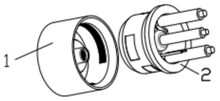
The invention provides a connecting terminal which comprises a female end frame and a male end frame, first reed grooves are symmetrically formed in the inner wall of the female end frame and used for containing a positive reed and a negative reed, a boss is arranged in the female end frame in the axial direction, second reed grooves are symmetrically formed in the outer circumferential face of the boss and used for containing a first signal reed and a second signal reed, the boss extends out of a shaft neck in the axial direction, and a third reed groove is formed in the surface of the inner circumference of the shaft neck and used for containing a ground wire reed. A first copper bar groove and a second copper bar groove are symmetrically formed in the outer circumferential surface of the male end frame, a positive electrode pre-connection copper bar and a negative electrode pre-connection copper bar are placed in the first copper bar groove, a positive electrode copper bar and a negative electrode copper bar are placed in the second copper bar groove, a third copper bar groove is symmetrically formed in the inner circumferential surface of the male end frame, a first signal copper bar and a second signal copper bar are placed in the third copper bar groove, a ground wire needle is fixed to the axis position of the male end frame, the connecting and disconnecting processes are achieved through longitudinal movement of the male end frame, the arc discharge prevention function is achieved through a mechanical movement mode instead of an electronic control signal, the structure is simple, and cost is low.

Description

technical field [0001] The invention relates to the technical field of electrical connectors, in particular to a connecting terminal capable of preventing arcing. Background technique [0002] Hot-plugging (hot-plugging or Hot Swap) is hot-plugging. The hot-plugging function allows users to take out and replace damaged hard disks, power supplies, batteries or boards without shutting down the system or cutting off the power supply. Improve the system's ability to recover from disasters in a timely manner. For high-current electrical interfaces, arcing is prone to occur during the process of plugging and unplugging. Traditional anti-arcing mainly uses two aspects: one is physical anti-arcing, that is, when connecting A physical isolation layer is provided in front of the pin of the connector to reduce the probability of arcing. The patent number is CN2019212924032, and the name is "A kind of anti-arcing pin and electrical connector". arcing at the tip of a needle, see figure...

Claims


Application Information

Patent Timeline
Patent Type & Authority Applications(China)
IPC IPC(8): H01R13/02
CPCH01R13/02
Inventor 曹伟李德胜郑隽一张育铭
Owner GUOCHUANG INNOVATION CENTER OF MOBILE ENERGY (JIANGSU) CO.,LTD.
Why Eureka
Try Eureka