Joint calibration system for internal and external parameters of camera
A technology of joint calibration, internal and external parameters, applied in image data processing, instruments, calculations, etc., can solve problems such as troublesome and inconvenient operation, and achieve the effect of accurate pose measurement results
- Summary
- Abstract
- Description
- Claims
- Application Information
AI Technical Summary
Problems solved by technology
Method used
Image
Examples
Embodiment 1
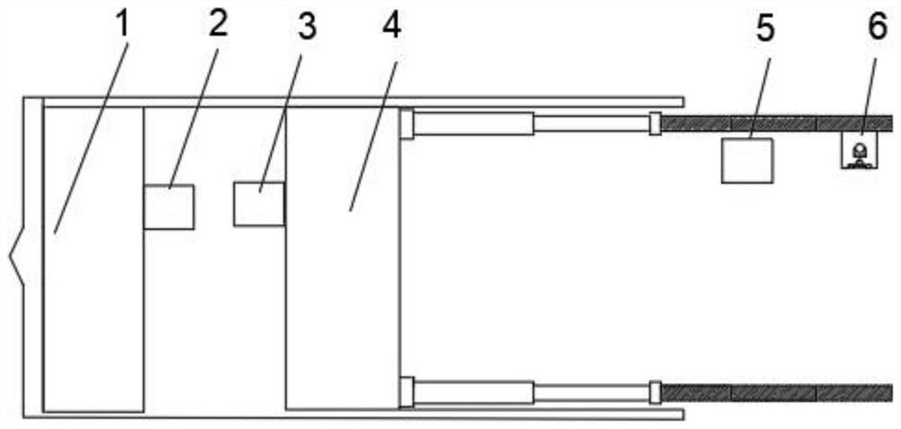
[0041] Such as Figure 1-6 As shown, this embodiment provides a joint calibration system for camera internal and external parameters, including: a calibration device (2), the calibration device (2) includes a light-emitting point (16), and the calibration device (2) is installed on the shield machine (4) Internal space;
[0042] A total station (5), the total station (5) is installed on the side wall of the tunnel where the external shield machine (4) is located; the total station (5) is located between the calibration device (2) and the Between the above-mentioned rearview prisms, it is used to obtain the total station (5) coordinates of the luminous point (16) under the total station (5) coordinate system;
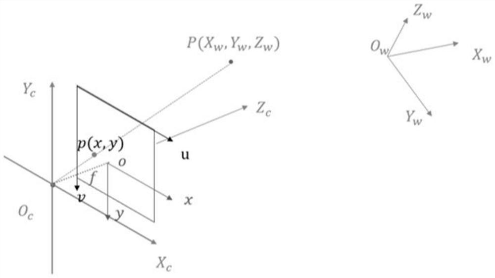
[0043] A camera (3), the camera (3) is installed on the support shield of the shield machine (4), for obtaining the camera (3) pixel coordinates of the light source in the camera (3) pixel coordinate system, and The parameters of the camera (3) are calibrated according...
Embodiment 2
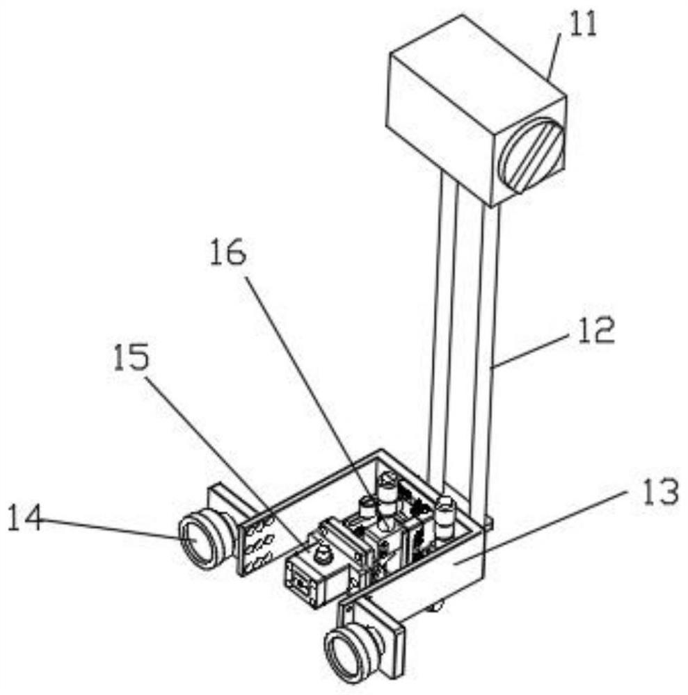
[0091] Such as Figure 1-6 As shown, this embodiment is based on Embodiment 1, and provides a camera internal and external parameter joint calibration system, including: the calibration device (2) specifically also includes: a small prism (14), used to assist the total station (5) to perform alignment.
[0092] Described calibration device (2) specifically also comprises: mounting bracket (13), and described mounting bracket (13) is U-shaped bracket; The quantity of described small prism (14) is two, is respectively installed on described mounting bracket ( 13) on the outside of the opening end of the U-shaped opening.
[0093] The small prism (14) and the light emitting point (16) are on the same axis. The luminous point (16) is arranged on the U-shaped bottom of the U-shaped bracket.
[0094] The calibration device (2) also includes a base (11), a connecting rod (12), and a three-dimensional lift (16); the mounting bracket (13) is fixed on the three-dimensional lift (16);...
Embodiment 3
[0100] Such as Figure 1-6 As shown, this embodiment is based on Embodiment 2, and provides a camera internal and external parameter joint calibration system, the luminous point includes a first luminous point fixing plate, a second luminous point fixing plate and a luminous point mounting seat; the first luminous point The point fixing plate is fixed to the second light-emitting point mounting plate by bolts; the gap between the first light-emitting point fixing plate and the second light-emitting point mounting plate is sealed; the first light-emitting point mounting plate is connected to the light-emitting point mounting seat gap seal. In this way, foreign dust and other sundries are prevented from entering the accommodation space through the gap between the light-emitting point mounting plate and the light-emitting point mounting seat.
PUM
 Abstract
Description
Claims
Application Information
 - Generate Ideas
- Intellectual Property
- Life Sciences
- Materials
- Tech Scout
- Unparalleled Data Quality
- Higher Quality Content
- 60% Fewer Hallucinations
Browse by: Latest US Patents, China's latest patents, Technical Efficacy Thesaurus, Application Domain, Technology Topic, Popular Technical Reports.
© 2025 PatSnap. All rights reserved.Legal|Privacy policy|Modern Slavery Act Transparency Statement|Sitemap|About US| Contact US: help@patsnap.com


