Gearbox state monitoring system

A state monitoring system and gearbox technology, applied in machine gear/transmission mechanism testing, electric components, electromechanical devices, etc., can solve the problems of magnetic interference, large additional space, small size, etc., and achieve high integration and reliability , strong power generation and power supply capabilities, and simple overall structure

Active Publication Date: 2021-05-25
ZHEJIANG NORMAL UNIVERSITY
View PDF6 Cites 0 Cited by
  • Summary
  • Abstract
  • Description
  • Claims
  • Application Information

AI Technical Summary

Problems solved by technology

Most of the self-powered monitoring systems proposed at present use the principle of electromagnetic and piezoelectricity to generate electricity. The disadvantages of electromagnetic power generation are the existence of magnetic interference and weak power generation capacity at low speeds. When it is too high, it will cause depolarization of piezoelectric ceramics
Obviously, the existing technology still has great limitations in practical application, and all kinds of transmission monitoring systems with self-powered monitoring functions that are small in size and highly integrated, especially suitable for high-temperature environments, are still urgently needed by various industries.

Method used


Image

  • Gearbox state monitoring system
  • Gearbox state monitoring system
  • Gearbox state monitoring system

Examples


Embodiment Construction

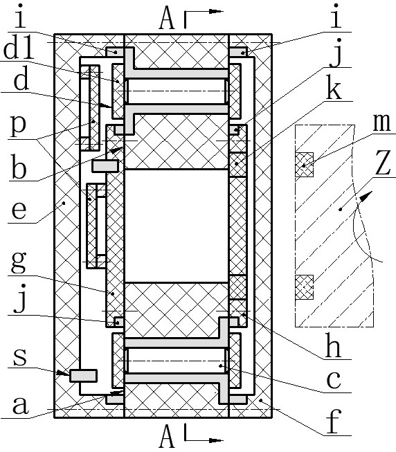
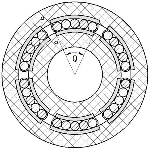
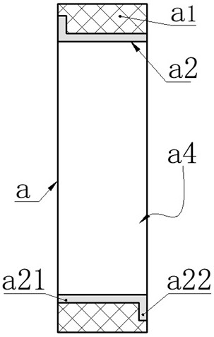
[0019] The present invention proposes a gearbox state monitoring system, which mainly includes a fixed coil a, a moving coil b, a roller c, a bracket d, a left housing e, a right housing f, a left baffle g, a right baffle h; The body e and the right case f are installed on both sides of the fixed coil a through screws, the left baffle g and the right baffle h are installed on both sides of the moving coil b through screws, and both the left case e and the right case f are equipped with There is a fixed electrode ring i, a moving electrode ring j is provided on the left baffle g and the right baffle h, and a circuit board p and a sensor s are installed on the left shell e and the left baffle g; A group of passive magnets k, the rotating shaft Z is inlaid with an active magnet m, the number and installation radius of the active magnet m and the passive magnet k are the same, and the opposite magnetic poles are installed oppositely; the roller c is installed between the fixed coil...


PUM


Abstract

The invention relates to a gearbox state monitoring system, and belongs to the technical field of self-powered monitoring and new energy. The left and right shells are arranged on two sides of the fixed ring, the left and right baffles are arranged on two sides of the movable ring, and the shells and the baffles are provided with circuit boards and sensors; active and passive magnets are respectively embedded on the rotating shaft and the right baffle, the rollers are arranged between the fixed ring and the movable ring and are divided into roller groups, the fixed ring consists of a fixed ring body and left and right fixed electrode groups, and the movable ring consists of a movable ring body and left and right movable electrode groups; the fixed electrode ring pressure and the movable electrode ring pressure are respectively connected to fixed terminals of the fixed electrode group or the movable electrode group close to the fixed electrode ring pressure; the rollers are in rolling contact with the movable and fixed electrodes to generate different inductive charges, potential differences exist between the left and right fixed and movable electrode groups, the roller groups are alternately contacted and separated from the electrodes in the fixed and movable electrode groups when the rollers rotate, the potential differences between the left and right fixed electrode groups and between the left and right movable electrode groups are alternately increased and decreased, and mechanical energy is converted into electric energy. The generated electric energy is supplied to the sensor, and parameters obtained by the sensor are transmitted out through the transmitting unit.

Description

technical field [0001] The invention belongs to the technical field of self-power supply monitoring and new energy, and in particular relates to a gearbox state monitoring system. Background technique [0002] Bearings, gears, axles, etc. are indispensable conventional parts in the fields of machine tools, vehicles, wind turbines, mining machinery and light industrial machinery, and are also the most vulnerable parts in related transmission systems. Because most of the components in the gearbox work in the environment of variable speed and variable load, they are prone to failure, and about 30% of the failures are caused by bearing failure; in addition, when the gearbox fails, it is difficult to repair and the cost is high. Transmission operation and maintenance costs are as high as 30% of the total operating costs. Therefore, various forms of transmission state real-time monitoring systems and methods have been proposed in order to obtain relevant state parameters of the t...

Claims


Application Information

Patent Timeline
IPC IPC(8): G01M13/02H02K7/18
CPCG01M13/02H02K7/1807Y02E10/72
Inventor 蒋永华张李刘盼盼阚君武王淑云程光明曾平吴鸣
Owner ZHEJIANG NORMAL UNIVERSITY
Why Eureka
Try Eureka