
Normal sewing machine

A flat car and sewing technology, applied in the field of sewing, can solve the problems of fabric squeezing and wrinkling, uneven fabric thickness, affecting the smoothness of the fabric, etc., and achieve the effect of smooth fabric and overall smoothness of the fabric.

Active Publication Date: 2021-05-25
中山市润凯制衣有限公司
View PDF8 Cites 0 Cited by
  • Summary
  • Abstract
  • Description
  • Claims
  • Application Information

AI Technical Summary

Problems solved by technology

[0005] Aiming at the deficiencies in the prior art, the purpose of the present invention is to provide a sewing flat car to solve the problems in the prior art due to the fact that the thickness of the convex stripe fabric is relatively large at the raised part, while the thickness of its connecting end is relatively small, resulting in different fabrics. The uneven thickness between the parts will be affected by gravity as the fabric is pushed, and the raised part will squeeze the part with a smaller thickness to the side, forming squeeze wrinkles between the fabrics, and then affecting the sewn fabric. flatness problem

Method used


Image

  • Normal sewing machine
  • Normal sewing machine
  • Normal sewing machine

Examples


Embodiment 1

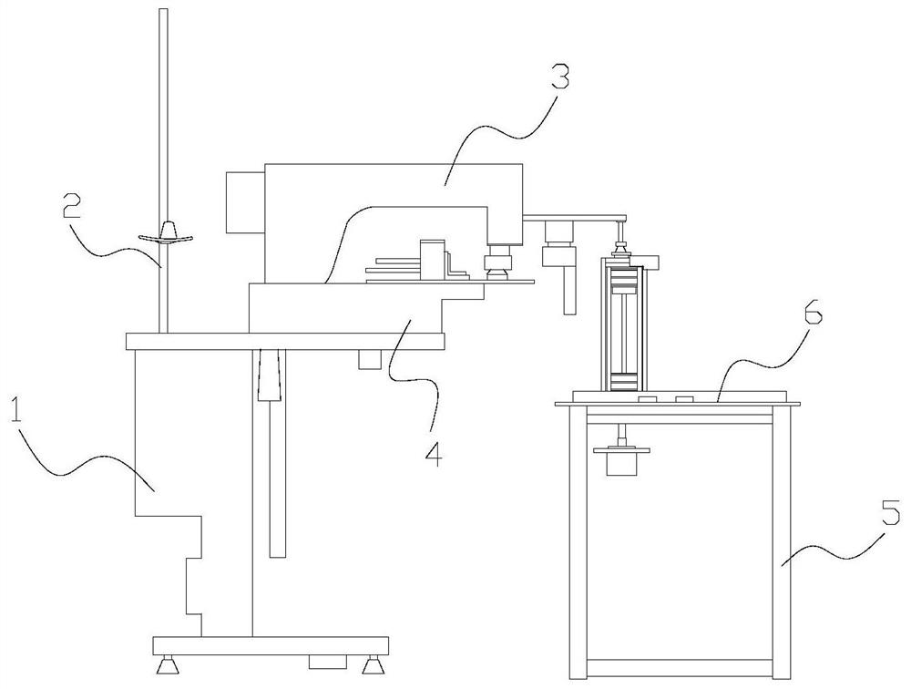
[0028] Example 1: Please refer to Figure 1-Figure 5 , the specific embodiments of the present invention are as follows:

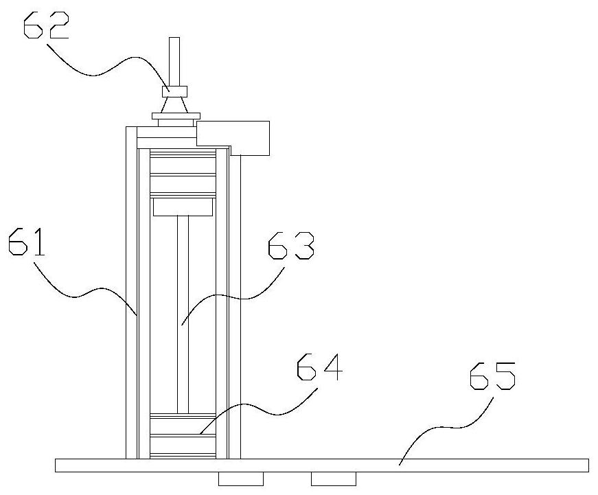
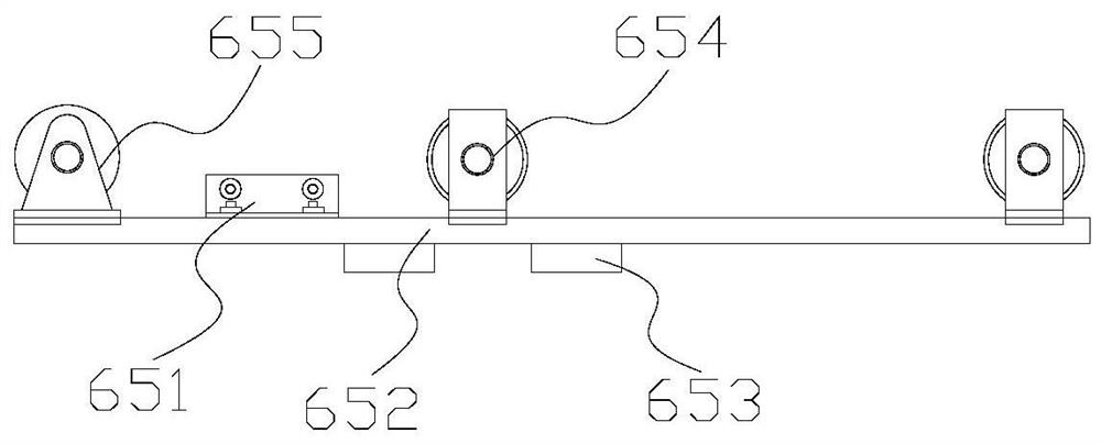
[0029] Its structure comprises a frame 1, a placement frame 2, a head 3, a workbench 4, an underframe 5, and a feeding structure 6. The placement frame 2 is vertically installed on the upper end of the frame 1 and is mechanically connected. The table 4 is horizontally installed on the upper end of the frame 1 and is fixedly connected, the machine head 3 is installed on the upper end of the workbench 4 and connected with each other, the bottom frame 5 is arranged on the right side of the frame 1, and the feeding structure 6 is installed horizontally At the upper end of the feeding structure 6 and mechanically connected, the upper left end of the feeding structure 6 communicates with the head 3 through a pipeline; the feeding structure 6 includes a cylinder 61, a gas pipe 62, a piston rod 63, a piston 64, and a conveying plate 65 The air pipe 62 is embedded...

Embodiment 2

[0035] Example 2: Please refer to Figure 5-Figure 8 , the specific embodiments of the present invention are as follows:

[0036] The adjustment roller 55b includes a rotating disk b1, a shaft hole b2, an outer ring b3, an adaptation groove b4, and a swing structure b5. The shaft hole b2 runs through the inside of the rotating disk b1 and is on the same axis. The outer ring b3 is installed on The outer side of the rotating disc b1 is fixedly connected, the adapting grooves b4 are recessed in the inner side of the outer ring b3 and evenly distributed, and the swing structure b5 is fixed on the outer side of the outer ring b3 and spaced between the adapting grooves b4.

[0037] refer to Figure 6 The swing structure b5 includes a fixed block b51, a rubber block b52, a rotating plate b53, and a rotating structure b54. The rubber block b52 is vertically installed on the lower end of the fixed block b51 and engaged with each other. The rotating plate b53 is installed on the fixed ...


PUM


Abstract

The invention discloses a normal sewing machine. The normal sewing machine structurally comprises a rack, a placement frame, a machine head, a workbench, an underframe and a feeding structure, wherein the placement frame is vertically installed at the upper end of the rack; the workbench is horizontally installed at the upper end of the rack; the machine head is installed at the upper end of the workbench; the underframe is arranged on the right side of the rack; the feeding structure is horizontally installed at the upper end of the feeding structure; the upper left end of the feeding structure communicates with the machine head through a pipeline; the feeding structure comprises an air cylinder, an air pipe, a piston rod, a piston and a conveying plate; the air pipe is embedded in the upper end of the air cylinder; the piston rod is embedded in the inner side of the air cylinder; the piston is arranged on the outer side of the piston rod in a sleeving mode; and the conveying plate is horizontally installed on the outer side of the piston. According to the invention, the conveying plate is arranged on the outer side of the piston rod, so that a connecting end between protruding parts is spread, a connecting end of a wrinkled part is unfolded, wrinkles formed by extrusion are reduced, and sewn cloth is smoother; and a swing structure is arranged on the outer side of an outer ring, so that the wrinkled part is better unfolded, and the whole cloth is smoother.

Description

technical field [0001] The invention belongs to the field of sewing, and in particular relates to a sewing flat car. Background technique [0002] The sewing flat car is mainly to sew and connect the fabrics to form the splicing between the fabrics. With the continuous increase of the types of fabrics and the continuous increase in people's demand for sewing products, the manual sewing flat car can no longer keep up with the current production speed. , and then it is necessary to use a sewing flat car for automatic feeding, so as to speed up the sewing between fabrics, but the prior art has the following deficiencies: [0003] Because the thickness of the protruding part of the convex striped fabric is relatively large, while the thickness of its connecting end is small, resulting in uneven thickness between different parts of the fabric. As the fabric is pushed, it will be affected by gravity, making the bulge The parts with smaller thickness are extruded to the side to fo...

Claims


Application Information

Patent Timeline
IPC IPC(8): D05B27/10D05B35/00
CPCD05B27/10D05B35/00
Inventor 张玉妹
Owner 中山市润凯制衣有限公司
Learn More