A panoramic imaging system and method based on a vehicle-mounted drill-and-blast tunnel

A panoramic imaging, vehicle-mounted technology, applied in the field of panoramic imaging systems, can solve problems such as affecting work efficiency, inaccurate surveying and mapping data, and taking a long time to achieve the effect of improving work efficiency, clear and reliable photos, and ensuring personnel safety.

Active Publication Date: 2022-03-25
SHANDONG UNIV
View PDF11 Cites 0 Cited by
  • Summary
  • Abstract
  • Description
  • Claims
  • Application Information

AI Technical Summary

Problems solved by technology

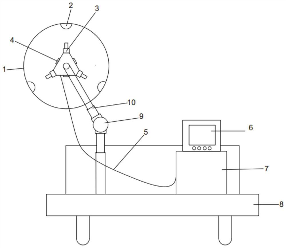
[0004] For the construction of tunnels, especially the construction of long tunnels, the acquisition and analysis of the development characteristics of cracks or joints in the surrounding rock mainly rely on methods such as on-site observation by testers, manual sketches, and test statistics. These traditional measurement methods are heavy workload, time-consuming, and serious Affects work efficiency and cannot adapt to current tunneling requirements
In recent years, some people have also adopted camera shooting methods to obtain images of surrounding rocks. However, the surrounding rocks at different heights in the tunnel restrict the testers from taking close-up shots, resulting in blurred images; limited by the imaging area of ​​a single camera, the photographed surrounding rock cracks or Incomplete joint imaging makes the surveying data inaccurate

Method used


Image

  • A panoramic imaging system and method based on a vehicle-mounted drill-and-blast tunnel
  • A panoramic imaging system and method based on a vehicle-mounted drill-and-blast tunnel
  • A panoramic imaging system and method based on a vehicle-mounted drill-and-blast tunnel

Examples


Embodiment Construction

[0047] The present disclosure will be further described below in conjunction with the accompanying drawings and embodiments.

[0048] It should be noted that the following detailed description is exemplary and intended to provide further explanation of the present disclosure. Unless defined otherwise, all technical and scientific terms used herein have the same meaning as commonly understood by one of ordinary skill in the art to which this disclosure belongs.

[0049] It should be noted that the terminology used herein is only for describing specific embodiments, and is not intended to limit the exemplary embodiments according to the present disclosure. As used herein, unless the context clearly dictates otherwise, the singular is intended to include the plural, and it should also be understood that when the terms "comprising" and / or "comprising" are used in this specification, they mean There are features, steps, operations, means, components and / or combinations thereof.

...


PUM


Abstract

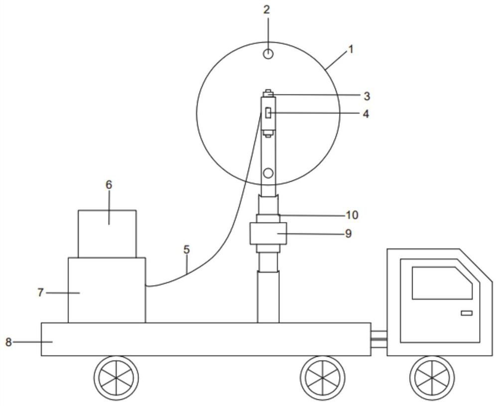
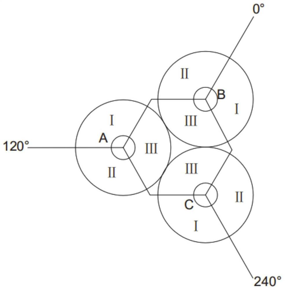
The present disclosure provides a panoramic imaging system and method based on a vehicle-mounted drilling and blasting tunnel, including a mobile vehicle, used for mobile measurement, and obtaining the test point position of surrounding rock imaging; an image acquisition system, including a spherical transparent protective shell, And the multiple cameras set in the spherical transparent protective shell are used to collect images of surrounding rocks in different directions at the corresponding test points; the moving mechanism is set on the mobile vehicle to carry the image acquisition system and drive the image acquisition system to move to the specified tunnel end face. Location; data transmission system, used to transmit the surrounding rock image at the collection point to the image processing system; image processing system, used to receive the surrounding rock image, process and stitch image information, and form a complete surrounding rock image at the corresponding imaging position. The disclosure can collect surrounding rock image data at different positions in the drilled and blasted tunnel, and process the image data to realize panoramic monitoring.

Description

technical field [0001] The disclosure belongs to the technical field of tunnel imaging, and in particular relates to a panoramic imaging system and method based on a vehicle-mounted drilling and blasting tunnel. Background technique [0002] The statements in this section merely provide background information related to the present disclosure and do not necessarily constitute prior art. [0003] In the process of tunnel construction, in order to analyze the development characteristics of cracks or joints in the surrounding rock, it is necessary to conduct on-site investigation of the surrounding rock in the tunnel, obtain the geological parameters of the tunnel surrounding rock, and monitor the tunnel surrounding rock to ensure the safety of the tunnel project. [0004] For tunnel construction, especially the construction of long tunnels, the acquisition and analysis of the development characteristics of surrounding rock cracks or joints mainly rely on methods such as on-sit...

Claims


Application Information

Patent Timeline
Patent Type & Authority Patents(China)
IPC IPC(8): H04N5/225H04N5/232H04N5/235H04N7/18
CPCH04N7/181H04N23/50H04N23/56H04N23/80H04N23/698H04N23/74
Inventor 潘东东李天昊石恒王朝阳李轶惠刘福民许振浩
Owner SHANDONG UNIV
Why Eureka
Try Eureka