Drive control circuit, control method and charge pump circuit

A technology for driving a control circuit and a charge pump, which is applied in the field of microelectronics and can solve problems such as high power consumption and reduced overall motor drive efficiency.

Pending Publication Date: 2021-05-18
XIAMEN KIWI MICROELECTRONICS TECH CO LTD
View PDF0 Cites 0 Cited by
  • Summary
  • Abstract
  • Description
  • Claims
  • Application Information

AI Technical Summary

Problems solved by technology

[0004] The existing technology requires two capacitors, and due to the continuous switching of the switch,...

Method used


Image

  • Drive control circuit, control method and charge pump circuit
  • Drive control circuit, control method and charge pump circuit

Examples


Embodiment Construction

[0055] Preferred embodiments of the present invention will be described in detail below in conjunction with the accompanying drawings.

[0056] In order to further understand the present invention, the preferred embodiments of the present invention are described below in conjunction with examples, but it should be understood that these descriptions are only to further illustrate the features and advantages of the present invention, rather than limiting the claims of the present invention.

[0057] The description in this part is only for several typical embodiments, and the present invention is not limited to the scope of the description of the embodiments. The mutual replacement of the same or similar prior art means and some technical features in the embodiments is also within the scope of the description and protection of the present invention.

[0058] "Coupling" or "connection" in the description includes both direct connection and indirect connection, such as connection ...


PUM


Abstract

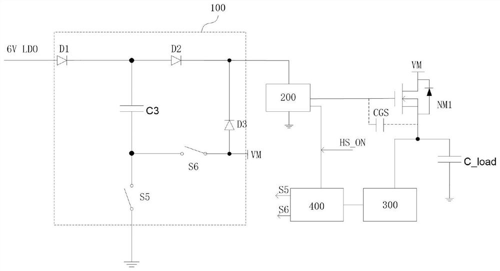
The invention discloses a drive control circuit, a control method and a charge pump circuit. The drive control circuit is used for driving a switching tube, comprises a first capacitor and can be coupled with a first power supply and a second power supply. When the driving control circuit is in a first working state, the driving control circuit controls the first capacitor to be coupled with the first power supply and controls the first power supply to charge the first capacitor; when the driving control circuit is in a second working state, the driving control circuit controls the switching tube to be coupled with the second power supply and controls the second power supply to supply power to the switching tube; and when the driving control circuit is in a third working state, the driving control circuit controls the first capacitor to be coupled with the control end of the switching tube and controls the first capacitor to supply power to the switching tube. According to the drive control circuit, the control method and the charge pump circuit, the circuit energy consumption can be reduced, and the circuit efficiency can be improved.

Description

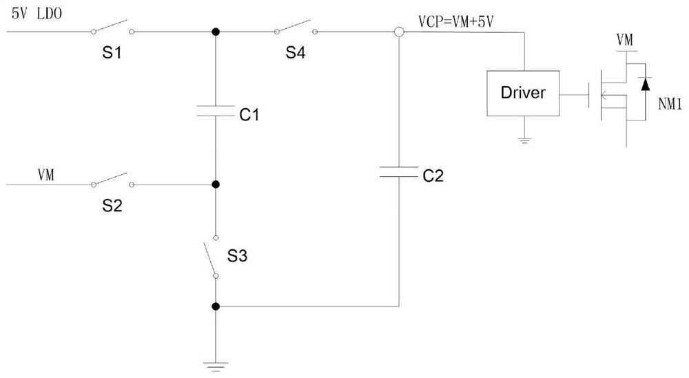
technical field [0001] The invention belongs to the technical field of microelectronics and relates to a driving circuit, in particular to a driving control circuit, a control method and a charge pump circuit. Background technique [0002] In motor drive, with the development of technology, it has become a trend to integrate power transistors and charge pumps inside the drive chip. The performance of the charge pump used to drive the N-type power transistor directly affects the efficiency and overall cost of the motor drive. [0003] The scheme of the existing charge pump circuit such as figure 1 As shown, in the first phase, the first switch S1 and the third switch S3 are closed, and the first capacitor C1 is charged by the 5V LDO (voltage regulator). In the second phase, the second switch S2 and the fourth switch S4 are closed, and the lower plate of the first capacitor C1 is connected to the input power supply VM. Since the voltage across the first capacitor C1 cannot c...

Claims


Application Information

Patent Timeline
IPC IPC(8): H02M3/07H02M1/08
CPCH02M1/08H02M3/07
Inventor 林官秋蔡坤明
Owner XIAMEN KIWI MICROELECTRONICS TECH CO LTD
Why Eureka
Try Eureka