
Intelligent boundary protection device

A protection device and intelligent technology, which is applied in the direction of emergency protection devices, emergency protection circuit devices, protection switches, etc., can solve the problems of consuming a lot of manpower and material resources, the failure of boundary switch equipment to quickly judge faults, and affecting the normal power supply of power distribution lines, etc.

Pending Publication Date: 2021-05-18
厦门昇立电子科技有限公司
View PDF0 Cites 0 Cited by
  • Summary
  • Abstract
  • Description
  • Claims
  • Application Information

AI Technical Summary

Problems solved by technology

[0003] The technical problem to be solved by the present invention is to provide an intelligent boundary protection device to solve the problem that the existing boundary switch equipment cannot quickly judge the fault, which requires a lot of manpower and material resources to eliminate it, and affects the normal power supply of the distribution line

Method used


Image

  • Intelligent boundary protection device
  • Intelligent boundary protection device
  • Intelligent boundary protection device

Examples


specific Embodiment 1

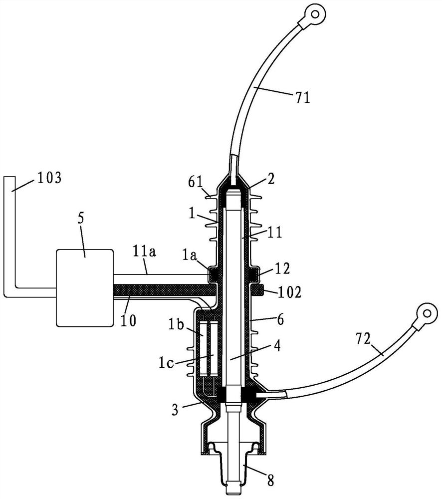
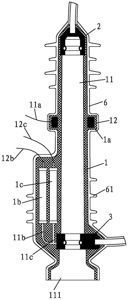
[0100] see Figure 1 to Figure 10 As shown, a preferred embodiment of an intelligent boundary protection device of the present invention includes a pole casing 1 having a receiving chamber 11, a sensor (not shown) arranged on the pole casing 1, and a The first conductive sleeve 2 on the upper part of the receiving chamber 11, the second conductive sleeve 3 located on the lower part of the receiving chamber 11, the fuse 4 installed in the receiving chamber 11 and the control connected to the sensor terminal 5; the upper end of the fuse 4 has a first conductive part 41 that is in contact with the first conductive sleeve 2 and a second conductive part 42 that is in contact with the second conductive sleeve 3 to realize the fuse 4 conduction.

[0101] In the present invention, sensors are arranged on the pole housing 1 of the demarcation protection device. Specifically, a variety of sensors can be arranged, so that the operating conditions in the power distribution line can be mo...

specific Embodiment 2

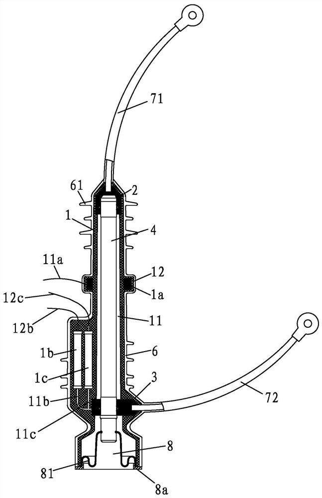
[0150] see Figure 3 to Figure 20 As shown, an intelligent boundary protection device of the present invention is different from the specific embodiment 1 in that the current sensor 1a in the specific embodiment 2 adopts an external method instead of being embedded in the pole shell 1, and other contents are the same as The specific embodiment 1 is the same and will not be described again here. On the one hand, the structural complexity of the pole housing 1 can be reduced by adopting the external method, which facilitates the pouring difficulty of the pole housing 1; It is also possible to facilitate replacement of the current sensor 1a without mounting it.

[0151] In this embodiment, the current sensor 1a is fixed on the middle part of the outer wall of the insulating casing 6 through the sensor hoop 9, so as to realize real-time collection and transmission of the current signal flowing through the fuse 4 .

[0152] In this embodiment, the middle part of the pole housing ...


PUM


Abstract

The invention provides an intelligent boundary protection device. The intelligent boundary protection device comprises a pole shell with a receiving cavity, a sensor arranged on the pole shell, a first conductive sleeve piece arranged on the upper portion of the receiving cavity, a second conductive sleeve piece arranged on the lower portion of the receiving cavity, a fuse installed in the receiving cavity and a control terminal connected with the sensor. And the upper end of the fuse is provided with a first conductive part which is in contact with the first conductive sleeve piece for electric conduction and a second conductive part which is in contact with the second conductive sleeve piece for electric conduction. The device has the advantages that the operation condition in the distribution line is monitored in real time through the power sensors in various combinations, and if an insulation grounding short circuit fault occurs in the distribution line, the control terminal can quickly and reliably study, judge and confirm the fault type and remotely transmit data information in real time, so that a fault point is quickly isolated. The power failure area is reduced, and adverse effects caused by large-area power failure are reduced; meanwhile, a power supply department can conveniently and quickly overhaul and remove faults, and power supply can be quickly recovered.

Description

【Technical field】 [0001] The invention relates to the field of power distribution protection equipment, in particular to an intelligent boundary protection device. 【Background technique】 [0002] The boundary switchgear is a kind of protection equipment used for distribution branch lines. When a fault occurs in the distribution line branch or the user side, if the relay protection action time limit of the boundary switchgear is different from the relay protection action time limit of the substation outlet switch of the power supply company Matching will cause the outlet switch of the substation to trip; because the traditional boundary switch equipment cannot quickly judge the fault, it takes a lot of manpower and material resources to troubleshoot and repair, and it will affect the normal power supply of the entire distribution line. In view of the above-mentioned problems, the inventor of this case conducted an in-depth study on the problem, and this case arose. 【Content...

Claims


Application Information

Patent Timeline
Patent Type & Authority Applications(China)
IPC IPC(8): H02H7/26H02H1/06H01H71/00H01H71/02H01H71/08H01H85/00H01H85/02H01H85/143H01H85/20
CPCH01H71/00H01H71/025H01H71/08H01H85/0013H01H85/0017H01H85/0078H01H85/02H01H85/143H01H85/2045H02H1/06H02H7/26H02H7/261
Inventor 赵菊芬
Owner 厦门昇立电子科技有限公司
Learn More