
Optical lens for aerospace

An optical lens and lens technology, applied in the field of aerospace optical lenses, can solve problems such as the inability to meet the radiation adaptability of the outer space environment, the impact and vibration requirements of the optical system for temperature changes, and the long-term work of the optical lens, so as to achieve good resistance to space charged particles Capability, guaranteed imaging clarity, low distortion effect

Active Publication Date: 2021-11-16
CHANGCHUN INST OF OPTICS FINE MECHANICS & PHYSICS CHINESE ACAD OF SCI
View PDF14 Cites 0 Cited by
  • Summary
  • Abstract
  • Description
  • Claims
  • Application Information

AI Technical Summary

Problems solved by technology

[0005] The object of the present invention is to provide a large field of view, low distortion, and adiabatic optical lens for aerospace, aiming to solve the problem that the optical lens cannot work for a long time in the outer space environment in the prior art, and cannot meet the radiation requirements of the outer space environment. Issues of adaptability, temperature changes, and shock vibration requirements for optical systems during satellite launches

Method used

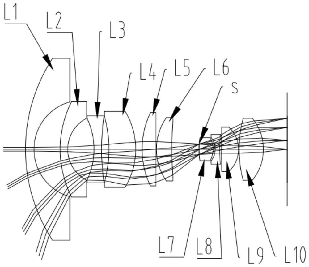
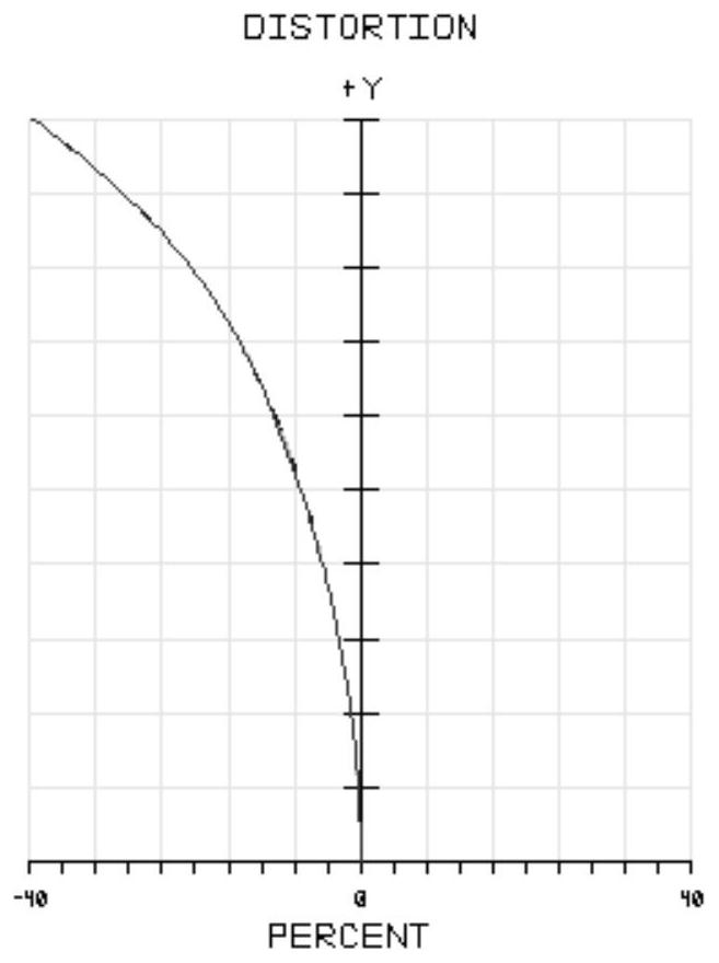
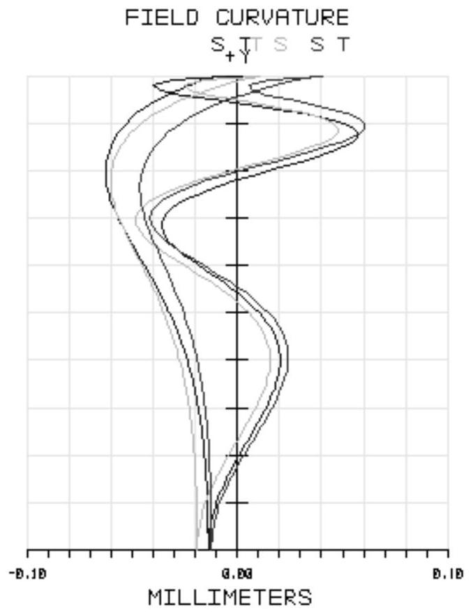

Image

  • Optical lens for aerospace
  • Optical lens for aerospace
  • Optical lens for aerospace

Examples


Embodiment Construction

[0031] In order to make the object, technical solution and advantages of the present invention clearer, the present invention will be further described in detail below in conjunction with the accompanying drawings and embodiments. It should be understood that the specific embodiments described here are only used to explain the present invention, not to limit the present invention.

[0032] It should be noted that when an element is referred to as being “fixed on” or “disposed on” another element, it may be directly on the other element or there may be an intervening element at the same time. When an element is referred to as being "connected to" another element, it can be directly connected to the other element or intervening elements may also be present.

[0033] In addition, it should be noted that the orientation terms such as left, right, up, and down in the embodiments of the present invention are only relative concepts or refer to the normal use status of the product, an...


PUM


Abstract

The invention discloses an optical lens for aerospace, comprising a first lens, a second lens, a third lens, a fourth lens, a fifth lens, a sixth lens, a diaphragm and a seventh lens arranged in sequence from the object side to the image side , the eighth lens, the ninth lens, the tenth lens, the first lens and the second lens are both negative meniscus lenses convex to the object side, the third lens is a negative meniscus lens or biconcave lens convex to the image side, the first lens The fourth lens is a positive meniscus lens convex to the image side, the fifth lens is a positive meniscus lens or plano-convex lens or biconvex lens convex to the object side, the sixth lens is a positive meniscus lens convex to the object side, and the seventh lens It is a double-convex lens, the eighth lens is a plano-concave lens or a double-concave lens, the ninth lens is a double-convex lens, and the tenth lens is a double-convex lens. The optical lens disclosed by the invention can realize large field of view, low distortion and adiabatic difference.

Description

technical field [0001] The invention relates to the technical field of optical design, in particular to an optical lens for aerospace. Background technique [0002] With the development of the aerospace industry to a higher level, for special space activities such as extravehicular activities of astronauts and spacecraft flight environments, it is necessary to install a camera device that can work in the outer space environment, and the optical system of the camera device must not only have In addition to the characteristics of large field of view and low distortion, it is also necessary to ensure that its imaging performance can remain stable under conditions such as aircraft landing, drastic temperature changes, and high-flux cosmic radiation. Impact resistance, temperature stability, radiation resistance, large field of view, and low distortion optical lenses for aerospace are necessary. [0003] The existing wide-angle optical system mostly adopts a multi-lens refractio...

Claims


Application Information

Patent Timeline
Patent Type & Authority Patents(China)
IPC IPC(8): G02B13/00G02B13/18G02B1/02G02B1/00
CPCG02B1/00G02B1/02G02B13/0045G02B13/006G02B13/18
Inventor 张新刘涛王灵杰史广维张建萍
Owner CHANGCHUN INST OF OPTICS FINE MECHANICS & PHYSICS CHINESE ACAD OF SCI
Learn More