
Thread axis gauge and thread part processing technology thereof

A thread axis and thread part technology, which is applied in the field of threaded hole position detection, can solve the problems of out-of-tolerance inspection tool accuracy, difficulty in manufacturing comprehensive inspection tools, and confusion in management.

Pending Publication Date: 2021-05-18
重庆新驰越动力设备有限公司
View PDF0 Cites 0 Cited by
  • Summary
  • Abstract
  • Description
  • Claims
  • Application Information

AI Technical Summary

Problems solved by technology

This method has the problem of large sampling errors, because the probe may obtain the maximum value or the minimum value when sampling the threaded inner hole, and the consistency of the sampling points is poor
[0004] The second method is to use the threaded mandrel for auxiliary measurement and evaluation, that is, to make the corresponding threaded mandrel according to the threaded hole specification, and the diameter of the mandrel is grouped according to the thread matching level. At present, the mandrels of each thread specification in the market are grouped as follows: 4 groups, screwed into the threaded holes in actual use, select the threaded mandrel with a small fit clearance according to the subjective judgment of the person, and then use the three coordinates to perform position evaluation and detection; this method has too many threaded mandrels, and the management It is confusing, and secondly, when using it, it is judged by human subjective consciousness to choose the matching gap, and there is a large human judgment error, which leads to the final result deviating from the actual size
However, this detection method has the difficulty of manufacturing comprehensive inspection tools and the problem that the accuracy of the inspection tool itself is out of tolerance. Secondly, this method can only judge whether the product position is qualified, and cannot judge the out-of-tolerance data of the specific direction position relative to the theoretical size.

Method used


Image

  • Thread axis gauge and thread part processing technology thereof

Examples


Embodiment

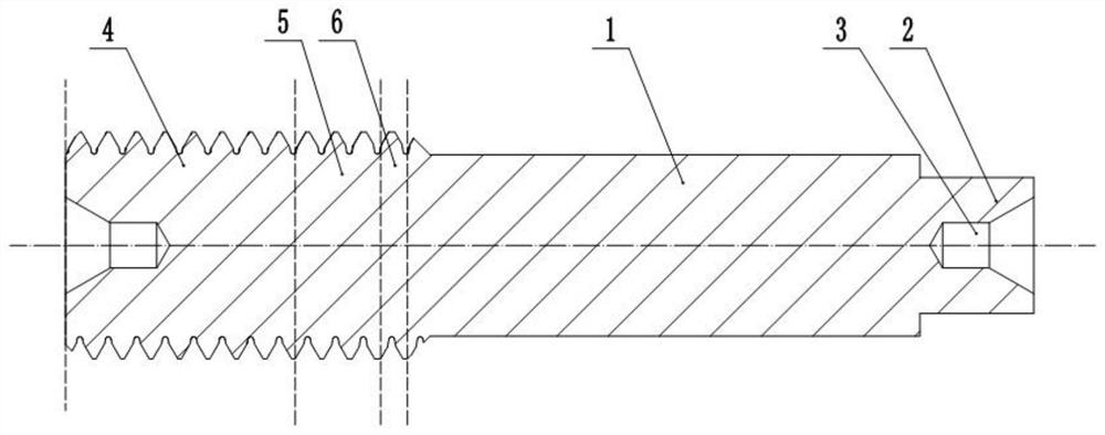
[0024] basically as attached figure 1 Shown: a thread axis gauge, comprising a threaded portion, a polished rod portion 1 and a mounting portion 2, the threaded portion, the polished stem portion and the mounting portion 2 are connected in sequence, the polished rod portion 1 is cylindrical, and the polished rod portion 1 is coaxial with the threaded portion, The end of the threaded portion and the end of the mounting portion 2 are provided with a central hole 3 coaxial with the polished rod portion 1 and the threaded portion, and the length of the mounting portion 2 is 5 mm.

[0025] The thread part includes a thread through end 4, a thread gradual change section 5 and a thread stop end 6 arranged in sequence, the thread stop end 6 is connected with the polished rod part 1, and the thread pitches of the thread through end 4, the thread gradual change section 5 and the thread stop end 6 are all P. , the major diameters of the thread through end 4, the thread gradual change sec...


PUM

PropertyMeasurementUnit
Lengthaaaaaaaaaa
Surface hardnessaaaaaaaaaa

Abstract

The invention relates to the technical field of threaded hole position accuracy detection, in particular to a thread axis gauge and a thread part processing technology thereof. The thread axis gauge comprises a thread part, a polished rod part and a mounting part which are sequentially connected, the polished rod part is cylindrical and is coaxial with the thread part, the thread part comprises a thread go end, a thread transition section and a thread not-go end which are sequentially arranged, the thread not-go end is connected with the polished rod part, the pitch diameter of the thread go end is d2 go, the pitch diameter of the thread not-go end is d2 not, and the pitch diameter of the thread transition section is gradually changed into the pitch diameter of the thread not-go end from the pitch diameter of the thread go end. According to the scheme, when the threaded part is screwed into the threaded hole, the axial clearance is continuously eliminated through the matching of the pitch diameters of the threads, the axial lead of the threads is found, and then detection is performed by matching with three coordinates, so that the position error of the threaded hole is judged.

Description

technical field [0001] The invention relates to the technical field of threaded hole position degree detection, in particular to a thread axis gauge and a thread part machining process thereof. Background technique [0002] Threaded connection is a relatively widely used connection method, so the detection of the position of the threaded hole is particularly important. At present, the position of the threaded hole is mainly detected by the following three methods: [0003] The first method is to use the three-coordinates to directly evaluate the points on the surface of the threaded hole, that is, to use the three-coordinate probe to collect points in the X and Y directions of the threaded inner hole, and fit it into a circle through the three-coordinate system software, and find The center of the circle is used to evaluate the positional degree with respect to the reference. This method has the problem of a large error in the point selection, because the probe may take th...

Claims


Application Information

Patent Timeline
IPC IPC(8): G01B5/00
CPCG01B5/00
Inventor 文发模张雪邓启国
Owner 重庆新驰越动力设备有限公司
Learn More