
Patsnap Eureka
For R&D, Patsnap Eureka makes reading and utilizing patents & technical documents easy.
Patsnap Eureka AIR
Designed for self-driven R&D workflows. Generate viable solutions, solve complex R&D challenges, empower your innovation with AI.

Patsnap Eureka Materials
Designed for material experts only. Revolutionize your material R&D, from search, analyze, to developing new materials.

TechResearch
Generate reliable direction feasibility study reports for your R&D in just a few steps.

TechSeek
Discover and master advanced knowledge NOW. Basics, ideas, possibilities, all at once.

TechMind
As an expert in R&D Theories, TechMind can generates customized viable solutions instantly.

TechRisk
Analyze your overall solution with one click, know your potential R&D risks in advance.

TechMonitor
Get weekly tech updates, stay abreast of the latest tech innovations and key insights.
Opposed type free piston engine
A piston engine, opposed technology, used in free piston engines, engine components, machines/engines, etc., can solve problems such as the inability to achieve air spring and piston rod compensation, the inability to change the relative position of the air spring, and the poor lubrication effect.
- Summary
- Abstract
- Description
- Claims
- Application Information
AI Technical Summary
Problems solved by technology
Method used
Image

Examples
Embodiment 1
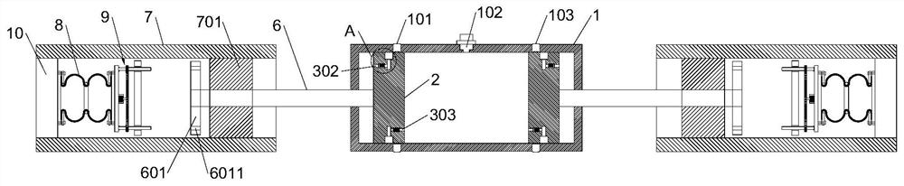
[0034]The opposed free-piston engine of the present invention comprises a combustion cylinder 1, an injection port 102 is arranged in the middle of the combustion cylinder 1, an air inlet 101 and an air outlet 103 are respectively arranged on both sides of the injection port 102, and the combustion cylinder 1 is symmetrical A piston body 2 is provided, the outer wall of the piston body 2 is provided with a lubricating mechanism 3 for storing lubricant, the outer side of the piston body 2 is connected with a piston rod 6, and the other end of the piston rod 6 runs through the side wall of the combustion cylinder 1 and is connected with a translation The plate 601 and the piston rod 6 are provided with an excitation coil 701 located between the translation plate 601 and the combustion cylinder 1. The periphery of the excitation coil 701 is provided with a coaxial induction coil 7, and the induction coil 7 is provided with a fixed plate 10 for fixing The plate 10 is provided with ...
Embodiment 2
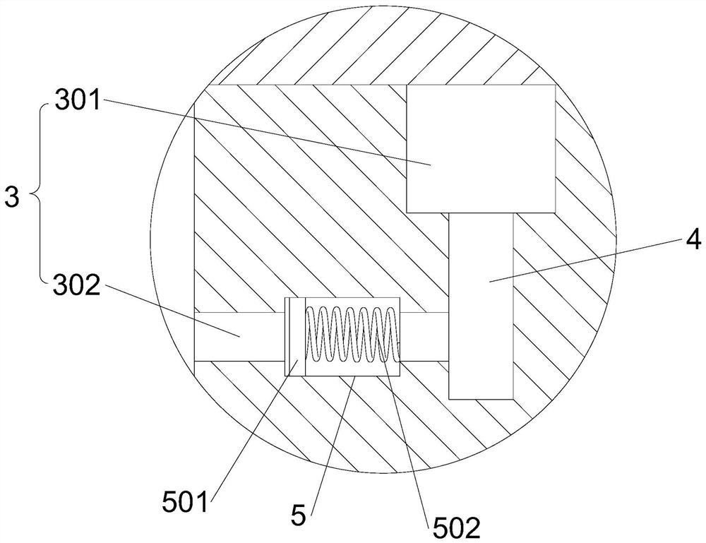
[0037] This embodiment is further optimized on the basis of Embodiment 1 as follows: the lubricating mechanism 3 includes an oil storage tank 301, a first guide hole 302 and a second guide hole 303; One end of the guide hole 302 and the second guide hole 303 communicate with the oil storage tank 301 , and the other ends of the first guide hole 302 and the second guide hole 303 respectively pass through the side walls on the left and right sides of the piston body 2 .
[0038] After adopting the above technical solution: by setting the first guide hole 302 and the second guide hole 303 , both the first guide hole 302 and the second guide hole 303 communicate with the oil storage tank 301 . The lubricant is stored in the oil storage tank 301, and the lubricant is viscous and has poor fluidity. When the piston body 2 is in the process of reciprocating motion, the gas pressure squeezes the first guide hole 302 or the second guide hole 303, so that the lubricant overflows from the ...
Embodiment 3
[0040] This embodiment is further optimized on the basis of Embodiment 1 as follows: the bottom wall of the oil storage tank 301 is provided with a communication groove 4 along the radial direction, the width of the communication groove 4 is smaller than the width of the oil storage tank 301, the first guide hole 302 and The second guide holes 303 are all arranged horizontally and communicate with the communication groove 4 .
[0041] After adopting the above technical scheme: by expanding the connecting groove 4 on the bottom wall of the oil storage tank 301, the width of the communication groove 4 is smaller than the width of the oil storage tank 301, reducing the minimum thrust forcing the lubricant to overflow outwards, ensuring that the piston body 2 is reciprocating During the movement, the lubricant can be forced to overflow and play the role of lubrication.
PUM
 Abstract
Description
Claims
Application Information
 - R&D Engineer
- R&D Manager
- IP Professional
- Industry Leading Data Capabilities
- Powerful AI technology
- Patent DNA Extraction
Browse by: Latest US Patents, China's latest patents, Technical Efficacy Thesaurus, Application Domain, Technology Topic, Popular Technical Reports.
© 2024 PatSnap. All rights reserved.Legal|Privacy policy|Modern Slavery Act Transparency Statement|Sitemap|About US| Contact US: help@patsnap.com