
Special-shaped beam formwork quick mounting and dismounting structure using electromagnetic force and mounting and dismounting method thereof

A special-shaped beam, electromagnetic force technology, applied in the direction of formwork/formwork member, formwork/formwork/work frame, formwork/formwork/work frame connector, etc., can solve problems such as material waste

Active Publication Date: 2021-05-18
CHINA CONSTR SECOND ENG BUREAU LTD
View PDF7 Cites 0 Cited by
  • Summary
  • Abstract
  • Description
  • Claims
  • Application Information

AI Technical Summary

Problems solved by technology

[0005] The purpose of the present invention is to provide a fast installation and disassembly structure of the special-shaped beam formwork using electromagnetic force and its installation and disassembly method, to solve the problem that a large amount of turnover materials need to be cut to set up a fixed scaffold when the special-shaped beam formwork is fixed, resulting in waste of materials

Method used


Image

  • Special-shaped beam formwork quick mounting and dismounting structure using electromagnetic force and mounting and dismounting method thereof
  • Special-shaped beam formwork quick mounting and dismounting structure using electromagnetic force and mounting and dismounting method thereof
  • Special-shaped beam formwork quick mounting and dismounting structure using electromagnetic force and mounting and dismounting method thereof

Examples


Embodiment Construction

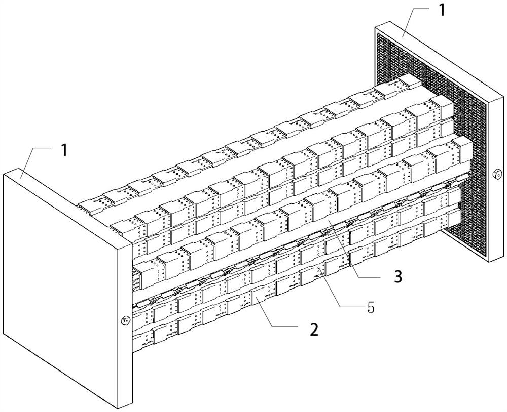
[0057] Examples see Figure 1 to Figure 4 As shown, the rapid installation and disassembly structure of special-shaped beam formwork using electromagnetic force and its installation and removal method,

[0058] The rapid installation and disassembly structure of the special-shaped beam formwork using electromagnetic force, including a pair of fixed plates 1, a shaped block 2 and a variable-angle fixed block 4 that are magnetically attracted between the pair of fixed plates 1 along the cross-sectional shape of the special-shaped beam and sandwiched between The template 3 between the shaping fast 2 and the variable angle fixed block 4.

[0059] see Figures 5 to 7 As shown, the fixed plate 1 includes a flat rectangular shell 1.1, a shoe-shaped iron core 1.2 arranged in the shell 1.1, a coil 1.3 wound on the shoe-shaped iron core 1.2, a controller 1.4 connected with the coil 1.3, and a controller 1.4 arranged on the control panel. The current stepless adjustment switch 1.5 on t...


PUM


Abstract

The invention relates to the field of building construction, in particular to a special-shaped beam formwork quick mounting and dismounting structure utilizing electromagnetic force and a mounting and dismounting method thereof. The special-shaped beam formwork quick mounting and dismounting structure comprises a pair of fixing plates 1, a shaping block 2, an angle-variable fixing block 4 and a formwork 3, wherein the shaping block 2 and the angle-variable fixing block 4 are magnetically attracted between the pair of fixing plates 1 along the cross section shape of a special-shaped beam, and the formwork 3 is clamped between the shaping block 2 and the angle-variable fixing block 4. The fixing plates 1 comprise flat rectangular shells 1.1, horseshoe-shaped iron cores 1.2 arranged in the shells 1.1, coils 1.3 wound on the horseshoe-shaped iron cores 1.2, controllers 1.4 connected with the coils 1.3 and current stepless regulating switches 1.5 arranged on the controllers 1.4. After the shells 1.1 are electrified, a magnetizer plate 1.6 is formed, and rectangular grids are drawn on the magnetizer plate 1.6. The shaping block 2 comprises an internal shaping block 2.1, an external end part shaping block 2.2 and an external standard shaping block 2.3; and a magnetizer block is formed after the shaping block 2 passes through. The problem that material waste is caused due to the fact that when the special-shaped beam formwork is fixed, a large number of turnover materials need to be cut to erect a fixed scaffold is solved.

Description

technical field [0001] The invention relates to the field of building construction, in particular to a fast installation and disassembly structure of a special-shaped beam template using electromagnetic force and an installation and removal method thereof. Background technique [0002] The special-shaped beam structure means that the shape of the cross-section of the beam is special-shaped, not the rectangle of the ordinary frame structure, such as rainbow beams, arc (curved) beams, etc. The on-site pouring process of the special-shaped beam structure is complicated, and the prefabrication cost is high, especially when the special-shaped beam structure inside the building is variable, the construction cost rises sharply. [0003] A magnet is a permanent magnet with a magnetic field around it, and the form of existence in its magnetic field space is a magnetic medium, and air, vacuum, or other substances are all magnetic media. In cement concrete, the hydrated tetracalcium a...

Claims


Application Information

Patent Timeline
IPC IPC(8): E04G13/04E04G17/00E04G9/08E04G9/10
CPCE04G13/04E04G17/00E04G9/08E04G9/10
Inventor 朱新博赵文科胡秋月何汗宇黄晨茜朱国鹏杨晓峰张飞王文龙郭耀张巧瑞
Owner CHINA CONSTR SECOND ENG BUREAU LTD
Learn More