


Quick Research
Generate reliable direction feasibility study reports for your R&D in just a few steps.

Technical Q&A
Discover and master advanced knowledge NOW. Basics, ideas, possibilities, all at once.

Find Solutions
As an expert in R&D theories, this can generate solutions to your technical problems instantly.

Evaluate Feasibility
Analyze your overall solution with one click, know your potential R&D risks in advance.

Monitor Landscape
Get weekly tech updates, stay abreast of the latest tech innovations and key insights.
Pollutant sampling device for water environment detection
A technology for sampling devices and pollutants, which is applied in the direction of sampling devices, measuring devices, sampling, etc., can solve the problems of complex structure of pollution devices, poor sealing of sewage, inconvenient portability, etc., and achieve simple structure, good sealing, and not easy to leak Effect
- Summary
- Abstract
- Description
- Claims
- Application Information
AI Technical Summary
Problems solved by technology
Method used
Image


Examples
Embodiment 1
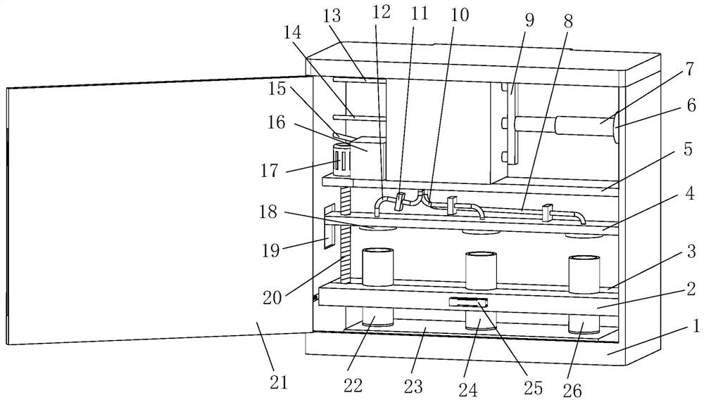
[0028] see Figure 1-6 , the present invention provides a technical solution: a pollutant sampling device for water environment detection, comprising a device body 1, the inner wall of the device body 1 is fixedly connected with a fixed plate 5, and the top of the fixed plate 5 is fixedly connected with a receiving plate 39, The inside of the receiving plate 39 is provided with a No. 1 pumping chamber 37, a No. 2 pumping chamber 35 and a No. 3 pumping chamber 34, and the insides of the No. 1 pumping chamber 37, the No. 2 pumping chamber 35 and the No. 3 pumping chamber 34 are all movably connected with a piston 36, The side wall of the piston 36 is fixedly connected with a slide rod 38, the slide rod 38 extends to the outside of the receiving plate 39 and is fixedly connected with the connecting rod 9, the inner wall of the device body 1 is fixedly equipped with a hydraulic device 6, and the output end of the hydraulic device 6 is fixedly connected There is a telescopic rod 7,...
Embodiment 2
[0031] Such as Figure 1-6 As shown, on the basis of Embodiment 1, the present invention provides a technical solution: the bottom of the device body 1 is fixedly connected with a bottom plate 23, and the inside of the bottom plate 23 is provided with three positioning holes 42, and the insides of the three positioning holes 42 are respectively inserted into No. 1 test tube 22, No. 2 test tube 24 and No. 3 test tube 26 are connected. The inner wall of the device body 1 is fixedly connected with a fixed splint 3. The side wall of the device body 1 is provided with a chute 44, and the device body 1 slides through the chute 44 provided. A slider 45 is connected, the side wall of the slider 45 is fixedly connected with a support spring 43, the outer wall of the slider 45 is fixedly connected with a movable splint 2, the outer wall of the movable splint 2 is fixedly connected with a handle 25, the fixed splint 3 and the movable splint 2 The opposite side walls are all provided with...
Embodiment 3
[0034] Such as Figure 1-6 As shown, on the basis of Embodiment 1 and Embodiment 2, the present invention provides a technical solution: a drive motor 17 is fixedly installed on the top of the fixed plate 5, and the output shaft of the drive motor 17 extends to the bottom of the fixed plate 5 and is fixed Connected with a threaded rod 20, the outer wall of the threaded rod 20 runs through and is threadedly connected with a slide plate 4, the bottom of the slide plate 4 is fixedly connected with three sealing covers 18, and the insides of the three sealing covers 18 are respectively fixedly connected with No. 1 water outlet pipe 12 and No. 2 outlet pipe. Water pipe 10 and No. 3 outlet pipe 8, No. 1 outlet pipe 12, No. 2 outlet pipe 10 and No. 3 outlet pipe 8 extend to No. 1 pumping cavity 37, No. 2 pumping cavity 35 and No. 3 pumping water respectively from the end of sealing cover 18 Inside the leakage groove 46 at the bottom of the chamber 34, the outer walls of the No. 1 wat...
PUM
 Abstract
Description
Claims
Application Information
 - R&D Engineer
- R&D Manager
- IP Professional
- Industry Leading Data Capabilities
- Powerful AI technology
- Patent DNA Extraction
Browse by: Latest US Patents, China's latest patents, Technical Efficacy Thesaurus, Application Domain, Technology Topic, Popular Technical Reports.
© 2024 PatSnap. All rights reserved.Legal|Privacy policy|Modern Slavery Act Transparency Statement|Sitemap|About US| Contact US: help@patsnap.com