
Air floatation device for sewage treatment

A sewage treatment and air flotation technology, applied in water/sewage treatment, flotation water/sewage treatment, water/sewage multi-stage treatment, etc., can solve the problems of reducing treatment effect, liquid level disturbance, affecting sewage treatment effect, etc.

Inactive Publication Date: 2021-05-14
杨光雪
View PDF1 Cites 0 Cited by
  • Summary
  • Abstract
  • Description
  • Claims
  • Application Information

AI Technical Summary

Problems solved by technology

[0003] Existing patent (notification number: CN 210117259U) discloses a kind of air flotation machine with good slag removal effect, comprising the air flotation machine tank; one side of the air flotation machine tank is fixedly connected with the first recovery assembly, the The other side of the tank body of the air flotation machine is fixedly connected with a second recovery assembly, and the top of the tank body of the air flotation machine is fixedly connected with a cleaning assembly. The inventor has found that at least the following problems have not been solved in the prior art: 1. The The air flotation form of the air flotation machine is single, which does not meet the requirements for the removal of suspended solids, resulting in poor removal of suspended solids in sewage treatment and affecting the sewage treatment effect; 2. The dissolved air water pressurized and aerated in the air flotation machine cannot It is fully mixed with sewage, resulting in a low utilization rate of dissolved air water, which wastes a lot of energy while reducing the treatment effect; 3. Although the air flotation machine has good slag removal efficiency, it uses the method of scraping slag to remove slag. It is easy to disturb the liquid surface and cause back-mixing of pollutants

Method used


Image

  • Air floatation device for sewage treatment
  • Air floatation device for sewage treatment
  • Air floatation device for sewage treatment

Examples


Embodiment Construction

[0025] In order to make the technical means, creative features, goals and effects achieved by the present invention easy to understand, the present invention will be further described below in conjunction with specific embodiments.

[0026] In the description of the present invention, it should be noted that the terms "upper", "lower", "inner", "outer", "front end", "rear end", "both ends", "one end", "another end" The orientation or positional relationship indicated by etc. is based on the orientation or positional relationship shown in the drawings, and is only for the convenience of describing the present invention and simplifying the description, rather than indicating or implying that the referred device or element must have a specific orientation, use a specific Azimuth configuration and operation, therefore, should not be construed as limiting the invention. In addition, the terms "first" and "second" are used for descriptive purposes only, and should not be understood ...


PUM


Abstract

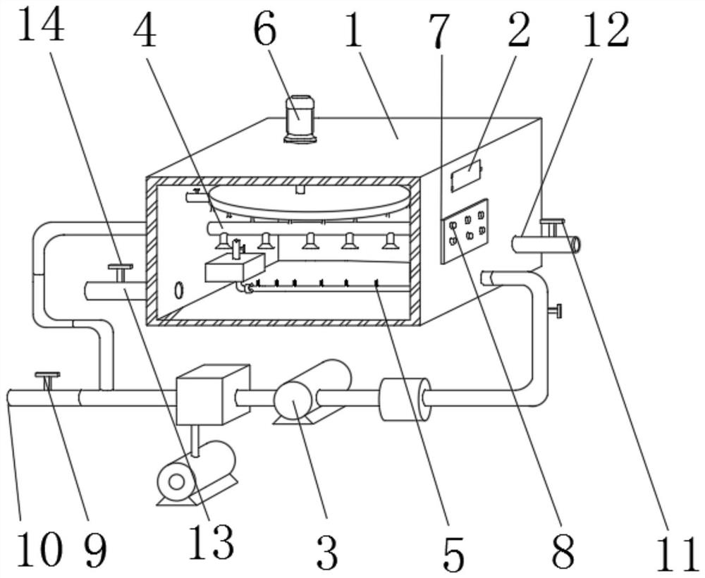
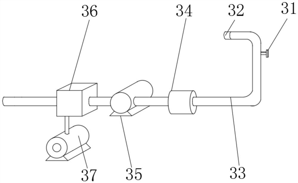
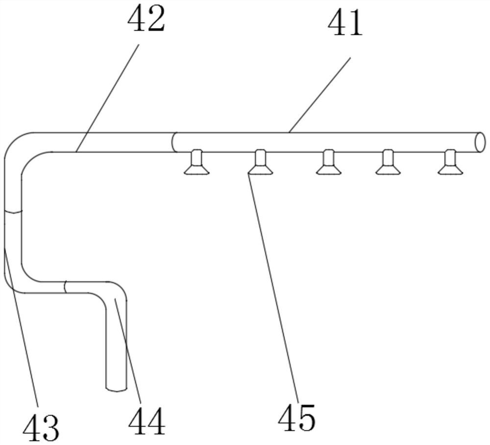
The invention discloses an air floatation device for sewage treatment. The air floatation device comprises a purification box, a slag removal device is fixedly mounted in the middle of the upper end of the purification box, an air-entrapping pressurization device is fixedly connected to the lower part of the right end of the purification box, and a sewage pipe and a distribution device are fixedly connected to the left end and the left part of the air-entrapping pressurization device respectively; and the right end of the distribution device penetrates through the left end wall of the purification box and extends into the purification box, and the left end of the purification box is fixedly connected with an electrolysis device. According to the air flotation device for sewage treatment, air flotation forms can be diversified through the air-entrapping pressurizing device, the distribution device and the ionization device, and the air flotation effect is improved; due to the design of a plurality of bent parts of the third bent pipe, the second bent pipe and the first bent pipe, the phenomenon that air-dissolved water is not uniformly mixed with sewage during single-end water distribution can be avoided, the utilization rate of the air-dissolved water is increased, and the energy consumption of the air flotation machine is reduced; in addition, disturbance to the liquid level is reduced through the slag removal device, and the pollutant backmixing phenomenon is avoided.

Description

technical field [0001] The invention relates to the technical field of sewage treatment, in particular to an air flotation device for sewage treatment. Background technique [0002] Sewage treatment: the process of purifying sewage to meet the water quality requirements for discharge into a certain water body or for reuse. Sewage treatment is widely used in various fields such as construction, agriculture, transportation, energy, petrochemical, environmental protection, urban landscape, medical care, catering, etc., and more and more enters the daily life of ordinary people. Now the sewage treatment process usually uses The air flotation machine removes the suspended solids in the sewage. [0003] Existing patent (notification number: CN 210117259U) discloses a kind of air flotation machine with good slag removal effect, comprising the air flotation machine tank; one side of the air flotation machine tank is fixedly connected with the first recovery assembly, the The other...

Claims


Application Information

Patent Timeline
IPC IPC(8): C02F9/06C02F1/24C02F7/00C02F1/461C02F1/40
CPCC02F1/001C02F1/24C02F1/40C02F1/46104C02F7/00C02F9/00Y02W10/10
Inventor 杨光雪
Owner 杨光雪
Learn More