Electric power unmanned aerial vehicle inspection path planning device
A technology for inspection paths and UAVs, applied in telephone structures, instruments, signal transmission systems, etc., can solve the problems of UAV electrical signals losing contact with battery life, increasing the risk of UAV loss and potential safety hazards, etc.
- Summary
- Abstract
- Description
- Claims
- Application Information
AI Technical Summary
Problems solved by technology
Method used
Image

Examples
Embodiment 1
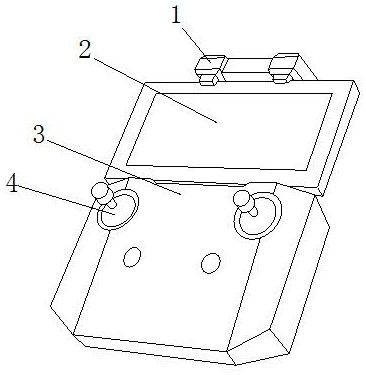
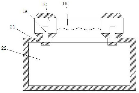
[0035] see Figure 1-Figure 8 , the present invention provides a power unmanned aerial vehicle inspection path planning device, its structure includes: capacitor column horizontal clip frame 1, mobile phone display screen 2, wireless remote control 3, rocker support 4, the capacitor column horizontal clip frame 1 is installed on the top of the mobile phone display screen 2 and is on the same vertical plane, the capacitive column horizontal clamp frame 1 is mechanically connected with the mobile phone display screen 2, and the mobile phone display screen 2 is installed on the top of the wireless remote control 3 and On the same slope, two rocker supports 4 are provided and both are inserted and embedded in the front side of the wireless remote controller 3, and the capacitor column horizontal clamping frame 1 is installed directly above the wireless remote controller 3, and the The capacitor column horizontal clamp frame 1 is provided with a capacitor column cap tube 1A, a fin ...
Embodiment 2
[0043] see Figure 1-Figure 8 , the present invention provides a power UAV inspection path planning device, other aspects are the same as Embodiment 1, the difference is:
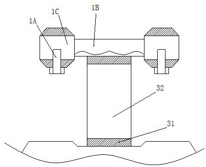
[0044] see image 3 , the wireless remote controller 3 is made up of a rubber gasket 31 and a bracket column plate 32, and the rubber gasket 31 is provided with two and installed on the upper and lower sides of the bracket column plate 32 respectively, and the rubber gasket 31 It is glued to the bracket column plate 32 and is on the same vertical surface, and the upper and lower ends of the bracket column plate 32 are edge-sealed by the rubber pad strip 31 to increase friction and prevent slippage.
[0045] see Image 6 , the rubber cushion strip 31 is composed of an arc flap rubber cushion block 311 and a transverse strip 312. The arc flap rubber cushion block 311 is provided with more than two and is installed inside the transverse strip 312. The arc The petal rubber pad 311 is closely attached to the ...
PUM
 Abstract
Description
Claims
Application Information
 - R&D
- Intellectual Property
- Life Sciences
- Materials
- Tech Scout
- Unparalleled Data Quality
- Higher Quality Content
- 60% Fewer Hallucinations
Browse by: Latest US Patents, China's latest patents, Technical Efficacy Thesaurus, Application Domain, Technology Topic, Popular Technical Reports.
© 2025 PatSnap. All rights reserved.Legal|Privacy policy|Modern Slavery Act Transparency Statement|Sitemap|About US| Contact US: help@patsnap.com