Imaging sensor image plane parallelism debugging system and method based on microscopic measurement

An imaging sensor and microscopic measurement technology, which is used in measurement devices, optical instrument testing, and optical performance testing, etc., can solve problems such as unfavorable accurate calculation, poor debugging accuracy, and large debugging workload, so as to improve assembly and debugging efficiency and ensure Batch quality, easy debugging effect

Active Publication Date: 2021-05-11
XI'AN INST OF OPTICS & FINE MECHANICS - CHINESE ACAD OF SCI +1
View PDF8 Cites 0 Cited by
  • Summary
  • Abstract
  • Description
  • Claims
  • Application Information

AI Technical Summary

Problems solved by technology

[0007] The purpose of the present invention is to solve the problem that the direct measurement method will scratch or damage the protective glass when debugging the parallelism of the image plane of the existing imaging sensor, and the non-parallel of the protective glass and the image plane leads to poor debugging accuracy, while the imaging measurement method has a large inclination Due to the blurred image quality when out of focus, which is not conducive to accurate calculation, and the technical problems of large debugging workload, a system and method for debugging the image plane parallelism of imaging sensors based on microscopic measurement are proposed. Based on the microscopic measurement technology of eccentricity meter, only the debugging sensor Components are measured, realizing non-contact measurement and digital measurement, greatly improving the efficiency of assembly and debugging, and ensuring batch quality

Method used


Image

  • Imaging sensor image plane parallelism debugging system and method based on microscopic measurement
  • Imaging sensor image plane parallelism debugging system and method based on microscopic measurement

Examples


Embodiment Construction

[0038] In order to illustrate the technical solution of the present invention more clearly, the present invention will be described in detail below in conjunction with the accompanying drawings and specific embodiments.

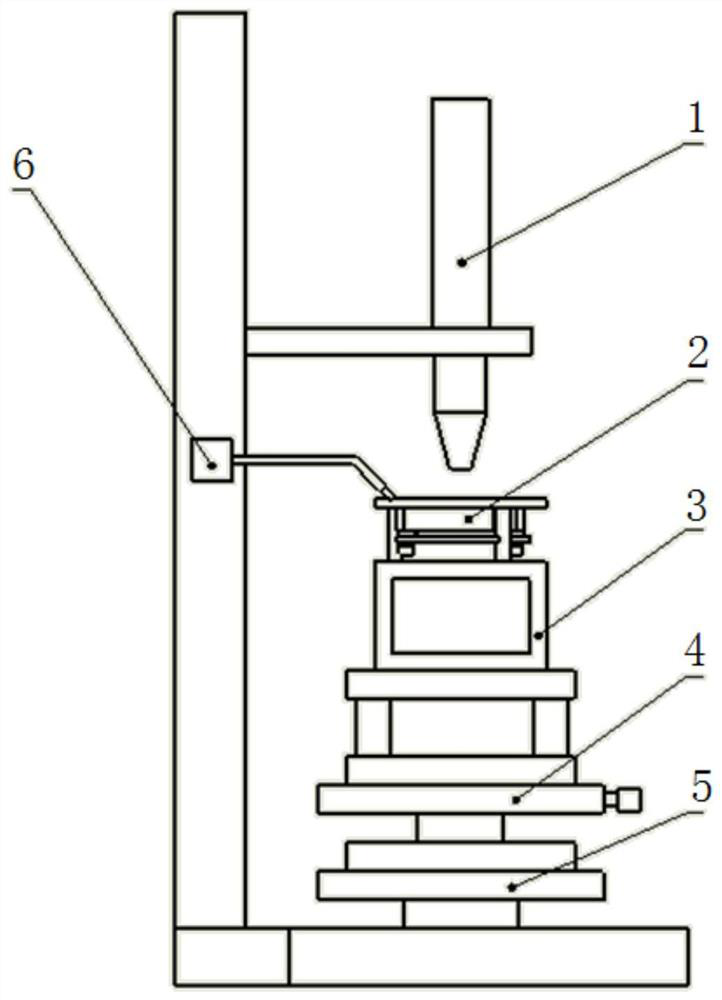
[0039] The measurement system used in the image plane parallelism debugging method based on microscopic measurement is as follows: figure 1 As shown, it includes an eccentricity instrument air bearing platform 5 , a four-dimensional adjustment table 4 , auxiliary tooling 3 , an eccentricity instrument imaging microscope 1 and a dial gauge 6 . The four-dimensional adjustment table 4 is set on the air-floating platform 5 of the eccentricity instrument, the auxiliary tooling 3 is set on the four-dimensional adjustment table 4 , and the sensor assembly 2 to be debugged is installed on the auxiliary tooling 3 . The eccentricity imaging microscope 1 and the dial gauge 6 are arranged on the support, and the eccentricity imaging microscope 1 is located directly above...


PUM


Abstract

The invention relates to an installation and adjustment method of an imaging sensor, particularly relates to an imaging sensor image plane parallelism debugging system and method based on microscopic measurement, and aims to solve the problems that when the image plane parallelism of an existing imaging sensor is debugged, protective glass is scratched or damaged by a direct measurement method, the debugging precision is poor, the out-of-focus image quality of an imaging measurement method is fuzzy so that accurate calculation is not facilitated, and a workload is large. The debugging system comprises an eccentric instrument air floating platform, a four-dimensional adjusting table, an auxiliary tool, an eccentric instrument imaging microscope and a dial indicator. A to-be-debugged sensor assembly is installed on the four-dimensional adjusting table, and the eccentric instrument imaging microscope is arranged right above the to-be-debugged sensor assembly. The debugging method based on the debugging system comprises the following steps: leveling the eccentric instrument air floating platform; leveling a mounting flange of the to-be-debugged sensor assembly; testing numerical values of three points of the imaging sensor by using the eccentric instrument imaging microscope, and calculating a deviation value; and correcting the thickness of a cushion column according to the deviation.

Description

technical field [0001] The invention relates to an installation and adjustment method of an imaging sensor, in particular to an imaging sensor image plane parallelism debugging system and method based on eccentricity meter microscopic measurement. Background technique [0002] Imaging sensors include CMOS, CCD, etc., which are installed at the back end of the optical lens of the star sensor to image the star target. The photosensitive image surface of the imaging sensor should be perpendicular to the optical axis in theory, and the imaging quality can be guaranteed only with a high installation accuracy index. with precision. [0003] The image surface of the imaging sensor is generally square or rectangular. The optical lens of the star sensor requires that the imaging quality must be guaranteed at each position of the image surface of the imaging sensor in different fields of view. For an optical lens with a large numerical aperture, the inclination of the image plane of ...

Claims


Application Information

Patent Timeline
Patent Type & Authority Applications(China)
IPC IPC(8): G01M11/04G01M11/02G01B11/26G01B5/24
CPCG01M11/04G01M11/0207G01M11/0257G01B11/26G01B5/24
Inventor 贾乃勋吴璀罡解来运卢振华王清龙孙雪琪栾超王曦邵雷
Owner XI'AN INST OF OPTICS & FINE MECHANICS - CHINESE ACAD OF SCI
Why Eureka
Try Eureka