An Ultra-Wideband High-Gain Dipole Antenna

A dipole antenna and high-gain technology, applied in the field of ultra-wideband high-gain dipole antennas, can solve problems such as poor reliability and manufacturability, failure to meet requirements, and low work efficiency

Active Publication Date: 2021-09-21
SOUTH CHINA UNIV OF TECH
View PDF4 Cites 0 Cited by
  • Summary
  • Abstract
  • Description
  • Claims
  • Application Information

AI Technical Summary

Problems solved by technology

[0005] The dipole antenna can be added with a back cavity to reduce the impact of the platform, but the work efficiency is low, and the reliability and manufacturability are poor
For application platforms that require high bandwidth and high gain, none of the existing technical solutions can meet the requirements

Method used


Image

  • An Ultra-Wideband High-Gain Dipole Antenna
  • An Ultra-Wideband High-Gain Dipole Antenna
  • An Ultra-Wideband High-Gain Dipole Antenna

Examples


Embodiment Construction

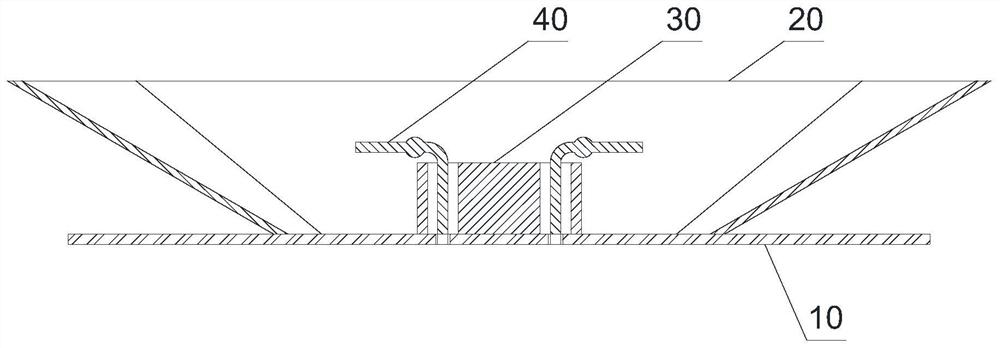
[0038] Such as Figure 1-4 As shown, the ultra-wideband high-gain dipole antenna of the present invention is made of metal as a whole: including a bottom plate 10 , an open back cavity 20 , an impedance matching module 30 and a dipole 40 . The structure of the antenna is very simple, no other medium is required except the metal structure, and it can play a huge role in the fields of wireless communication and high-resolution radar detection.

[0039] The middle part of the bottom plate 10 is provided with two feed ports 11 connecting the upper and lower surfaces.

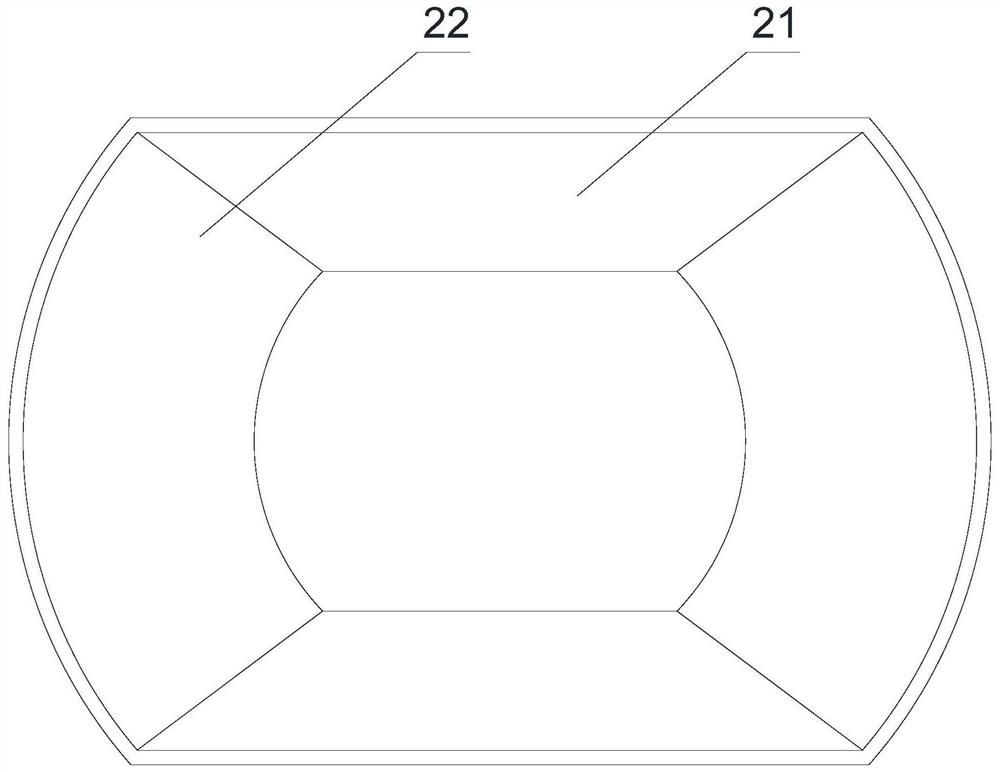
[0040] The lower port of the open back chamber 20 is fixedly connected to the upper surface of the bottom plate 10, and the upper port expands outward. It is formed by two oppositely arranged side plates 21 and two oppositely arranged arc plates 22 mutually spaced and enclosed. The side plate 21 is an inverted trapezoid and forms a non-zero angle with the bottom plate 10 , and the angle between the plane of the si...


PUM


Abstract

The invention discloses an ultra-broadband high-gain dipole antenna, relates to components of wireless communication equipment, and proposes the proposal aiming at the problems of insufficient bandwidth and gain in the prior art. Including the bottom plate, the open back cavity and the dipole; the lower port of the open back cavity is fixedly connected to the upper surface of the bottom plate, and the upper port expands outward; the dipole is set in the middle of the lower port of the open back cavity and connected to the feed port of the bottom plate Electrical connection; the two electromagnetic poles in the dipole have a symmetrical structure: they are respectively composed of vertical rods, arc rods and horizontal rods connected in sequence, and the horizontal rods of the two electromagnetic poles extend away from each other. The position is provided with spherical protrusions. The advantage is that the impedance bandwidth from 4.1GHz to 14.3GHz is realized, covering all of the C-band and X-band, and a small part of the Ku-band. The antenna gain within the bandwidth can reach 10-18.7dBi, and the overall solution realizes ultra-wideband high-gain radiation, which is especially suitable for radar technology.

Description

technical field [0001] The invention relates to components of wireless communication equipment, in particular to an ultra-wideband high-gain dipole antenna. Background technique [0002] With the rapid development of wireless communication technology, the requirements for antennas of wireless communication systems are also constantly improving. In order to accommodate the original frequency bands and increasing frequency bands at the same time, such as PCS, LTE, WLAN, Sub 6G, etc., the antenna should have more Wide working frequency band. [0003] The dipole antenna achieves the same radiation pattern in the two polarization planes, and has a series of good characteristics such as low back lobe, low cross polarization, and stable gain. However, there are many deficiencies in the existing technology. First, only the most basic dipole structure is used, so that its impedance bandwidth and axial ratio bandwidth are narrow, and it can only cover the most basic communication fre...

Claims


Application Information

Patent Timeline
Patent Type & Authority Patents(China)
IPC IPC(8): H01Q5/25H01Q1/36H01Q1/50
CPCH01Q1/36H01Q1/50H01Q5/25
Inventor 张洪林钟海权傅祯湛陈志坚
Owner SOUTH CHINA UNIV OF TECH
Why Eureka
Try Eureka