Infusion and oxygen delivery system for emergency department
An emergency and oxygen delivery technology, which is applied in the field of infusion and oxygen delivery systems for emergency departments, can solve the problems of emergency beds not equipped with infusion and oxygen delivery, slipping of plastic tubes, delaying treatment time, etc., so as to increase the first aid function and scope, and ensure the firmness of the connection , the effect of saving first aid time
- Summary
- Abstract
- Description
- Claims
- Application Information
AI Technical Summary
Problems solved by technology
Method used
Image
Examples
Embodiment 1
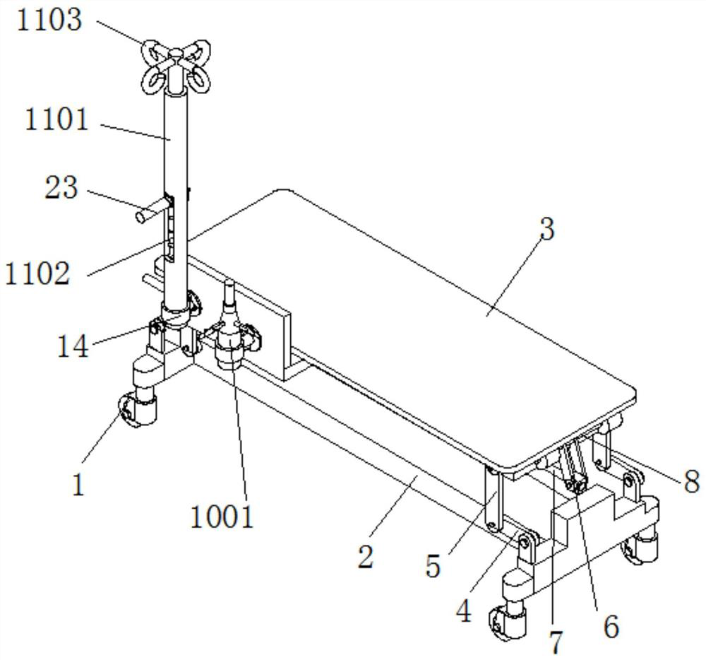
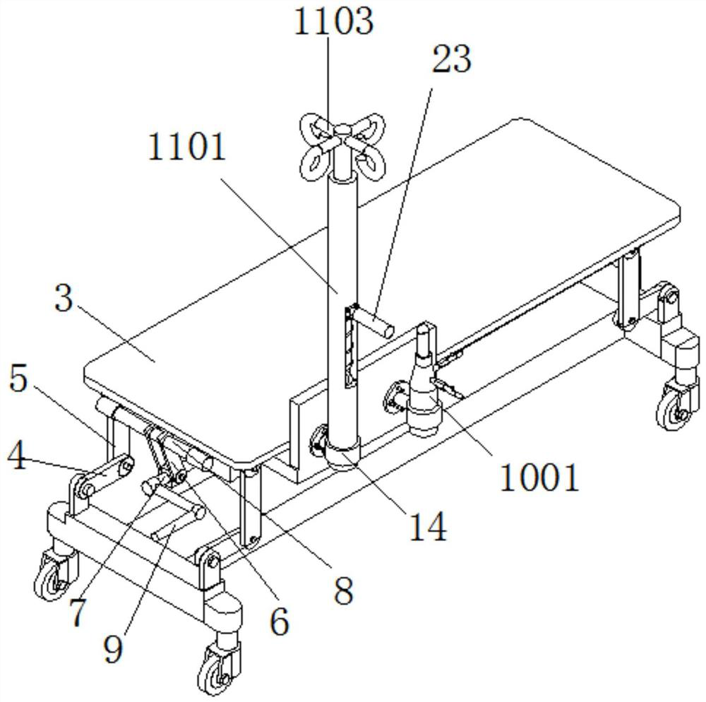
[0029] Embodiment 1 has introduced a kind of infusion oxygen delivery system for emergency department, as Figure 1-2As shown, it includes an infusion and oxygen delivery system for emergency department, including universal wheel 1, base 2, bed board 3, movable connecting plate one 4, movable connecting plate two 5, connecting seat plate 6, adjusting screw rod one 7, and fixed shaft 8 And the adjustment handle 9; the emergency department infusion oxygen delivery system also includes an oxygen delivery assembly 10 and an infusion assembly 11;
[0030] The four corners of the lower surface of the base 2 are fixedly connected with four sets of universal wheels 1, the four corners of the upper surface of the base 2 are respectively hinged with movable connecting plates 1 4, and the four corners of the lower surface of the bed board 3 are respectively hinged with movable connecting plates 2 5, The first movable connecting plate 4 and the second movable connecting plate 5 are hinged...
Embodiment 2
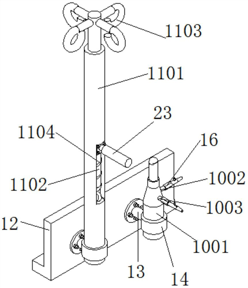
[0035] Embodiment 2 is an improvement on the basis of Embodiment 1, as Figure 9-10 As shown, wherein, the infusion set 11 includes a fixed support sleeve 1101, a movable support rod 1102, a hook 1103 and a spring 1104, and the fixed support sleeve 1101 is fixedly connected to the mounting seat plate 12 through the lifting rod 13 and the lifting ring 14, and the fixed support The sleeve 1101 is provided with a through hole 3 18 extending axially along the fixed support sleeve 1101; A number of hooks 1103 are fixedly connected; a spring 1104 is also provided inside the fixed support sleeve 1101, the bottom end of the spring 1104 is fixedly connected to the bottom end of the fixed support sleeve 1101, and the top end of the spring 1104 is fixedly connected to the bottom end of the movable support rod 1102.
[0036] In this embodiment, the lifting rod 13 and the lifting sleeve in the present invention work together to support the fixed support sleeve 1101, and the movable support...
Embodiment 3
[0038] Embodiment 3 is an improvement on the basis of Embodiment 1, as Figure 11-12 The movable support rod 1102 shown includes a supporting part 1102A and a mounting part 1102B. The supporting part 1102A is located directly above the mounting part 1102B. A hook 1103 is fixedly connected to the top of the supporting part 1102A. The guide block 22 is sheathed on the installation part 1102B, and the guide block 22 and the installation part 1102B are fixedly connected by bolts. The outer wall of the support portion 1102A is in close contact with the inner wall of the fixed support sleeve 1101 , and the guide block 22 is in close contact with the third through hole 18 . When the spring 1104 is in a natural state, the guide block 22 is just engaged with the top end of the through hole 3 18; the handle 23 is fixedly connected to the guide block 22 .
[0039] In this embodiment, by setting the spring 1104 and defining that when the spring 1104 is at its natural length, the guide bl...
PUM
 Abstract
Description
Claims
Application Information
 - R&D Engineer
- R&D Manager
- IP Professional
- Industry Leading Data Capabilities
- Powerful AI technology
- Patent DNA Extraction
Browse by: Latest US Patents, China's latest patents, Technical Efficacy Thesaurus, Application Domain, Technology Topic, Popular Technical Reports.
© 2024 PatSnap. All rights reserved.Legal|Privacy policy|Modern Slavery Act Transparency Statement|Sitemap|About US| Contact US: help@patsnap.com


